Method of manufacturing electrocatalyst through one step electrodeposition and electrocatalyst manufactured therefrom

a manufacturing method and electrocatalyst technology, applied in the direction of electrocatalysts, physical/chemical process catalysts, multiple component coatings, etc., can solve the problems of complex manufacturing process, inefficient in cost, process may not be simplified, etc., to reduce the use of additives and simplify the process of manufacturing.

Inactive Publication Date: 2020-02-20
HYUNDAI MOTOR CO LTD +2
View PDF0 Cites 7 Cited by
  • Summary
  • Abstract
  • Description
  • Claims
  • Application Information

AI Technical Summary

Benefits of technology

[0009]In preferred aspect, the present invention may provide simplified process of process of manufacturing an electrocatalyst and reduce an additive used in electrodeposition. In addition, the present invention may provide the process of manufacturing the electrocatalyst to remove moisture.

Problems solved by technology

However, since platinum corresponds to a noble metal and has a limitation on reserves, studies on using a metal rich in reserves, such as iron (Fe), nickel (Ni), copper (Cu), and cobalt (Co) as an element to replace platinum, particularly, studies on using a heterogeneous metal as a material for an electrocatalyst have been actively conducted.
However, a manufacturing process is complicated with being subjected to a carbonization process at 800° C. and a post-heat treatment process at 300° C. using a metal-organic framework (MOF) as a precursor and only the activity in a strong base (pH 13.5) electrolyte has been reported.
In addition, in the related arts, a material in which a nickel (Ni) foam has been doped with cobalt, which may involve a complicated process such as formation of a layered nanostructure (three-layered morphology) on the surface of the nickel foam using a sphere lithography process.
However, the addition of phosphorus requires a process at 300° C., and thus is not efficient in terms of costs.
Further, because additives for various purposes are used, such as the use of SDS and Na2SO4 as an ion strengthening agent and the use of aqueous ammonia as a pH adjusting agent, the process may not be simplified.

Method used


Image

  • Method of manufacturing electrocatalyst through one step electrodeposition and electrocatalyst manufactured therefrom
  • Method of manufacturing electrocatalyst through one step electrodeposition and electrocatalyst manufactured therefrom
  • Method of manufacturing electrocatalyst through one step electrodeposition and electrocatalyst manufactured therefrom

Examples


example

[0100]Hereinafter, a process of manufacturing a Ni91Cu9—P catalyst layer as the Example of the present invention will be described in detail. However, the Examples described below are only provided for specifically exemplifying or explaining the present invention, and the present invention is not limited thereby.

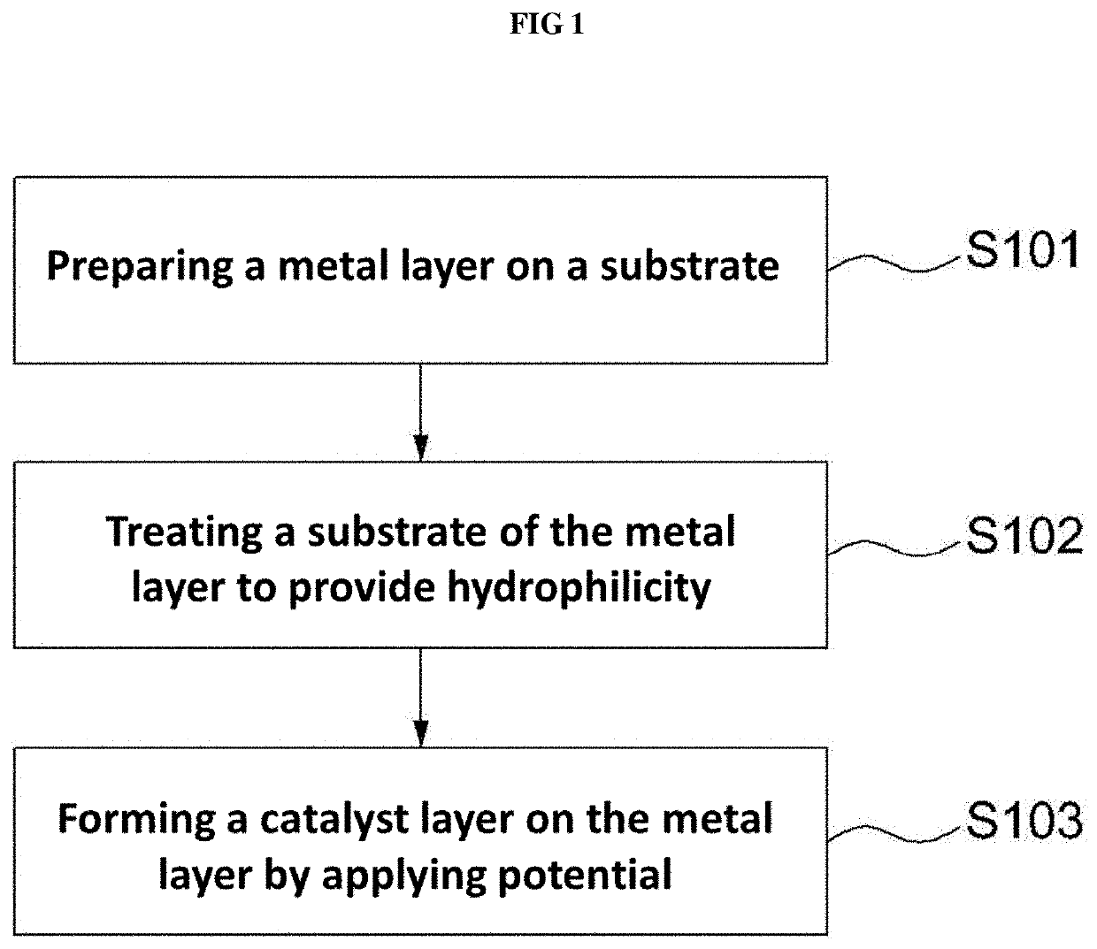
[0101]A nickel layer was formed to have a thickness of 50 nm on a silicon wafer by using an electron beam deposition apparatus, and the substrate was subjected to hydrophilic surface treatment with a UV ozone cleaner (AC-6, 15 to 20 mW / cm2) for 10 minutes.

[0102]An aqueous deposition solution was prepared by mixing nickel sulfate, copper sulfate, and sodium hypophosphite, which are a nickel precursor, a copper precursor, and a phosphorus precursor, respectively, and sodium acetate and citric acid, which are additives with distilled water. The molar ratio of the nickel precursor to the copper precursor was adjusted to 199:1, the molar ratio of the nickel precursor to each addi...


PUM

PropertyMeasurementUnit
molar concentrationaaaaaaaaaa

Abstract

Disclosed is a method of manufacturing an electrocatalyst. The method may include forming a metal layer on a substrate, treating a substrate of the metal layer, and forming a catalyst layer on the metal layer by applying potential to an aqueous deposition solution including a nickel precursor, a copper precursor, a phosphorus precursor, and an additive, in which a molar ratio of the nickel precursor to the copper precursor may be greater than about 49:1. Accordingly, the present invention has an advantage in that the process of manufacturing the electrocatalyst may be simplified.

Description

CROSS-REFERENCE TO RELATED APPLICATIONS[0001]This application claims priority under 35 U.S.C. § 119 to Korean Patent Application No. 10-2018-0095514, filed on Aug. 16, 2018, in the Korean Intellectual Property Office, the disclosure of which is incorporated herein by reference in its entirety.FIELD OF THE INVENTION[0002]The present invention relates to a method of manufacturing an electrocatalyst by electrodeposition.BACKGROUND OF THE INVENTION[0003]Since the current hydrogen energy has received attention as an eco-friendly energy capable of replacing fossil fuels and the hydrogen energy can be produced only by electrolysis of water, interests in studies on an electrocatalyst that produces hydrogen energy by electrolyzing water have been increased.[0004]Typically, the electrocatalyst is composed of a hydrogen evolution reaction (HER) electrode and an oxygen evolution reaction (OER) electrode. Platinum (Pt) has been the most widely known as a material for each electrode. However, sin...

Claims


Application Information

Patent Timeline
Patent Type & Authority Applications(United States)
IPC IPC(8): C25B11/04C25B1/04
CPCC25B11/0478C25B1/04B01J27/1853B01J35/0033C25B11/075C25D3/562C25D21/04C25D5/18Y02E60/36C25B11/059C25B11/057C25B11/091C25D5/625C25D5/617
Inventor PARK, JANG-SUHWANG, YOUNG-EUNBAIK, JEONG MINKIM, HEE JUNLEE, TAE WON
Owner HYUNDAI MOTOR CO LTD
Why Eureka
Try Eureka