

Lead carbon battery comprising an activated carbon anode
a technology lead carbon battery, which is applied in the direction of batteries, cell components, electrical appliances, etc., can solve the problems of low discharge capacity, low discharge capacity, and difficulty in achieving a high number of charge-discharge cycles. , to achieve the effect of increasing the porosity of activated carbon anode, less specific capacity, and increasing discharge capacity
- Summary
- Abstract
- Description
- Claims
- Application Information
AI Technical Summary
Benefits of technology
Problems solved by technology
Method used
Image

Examples
example 1
on of an Activated Carbon Anode Using a Phase Inversion Technique
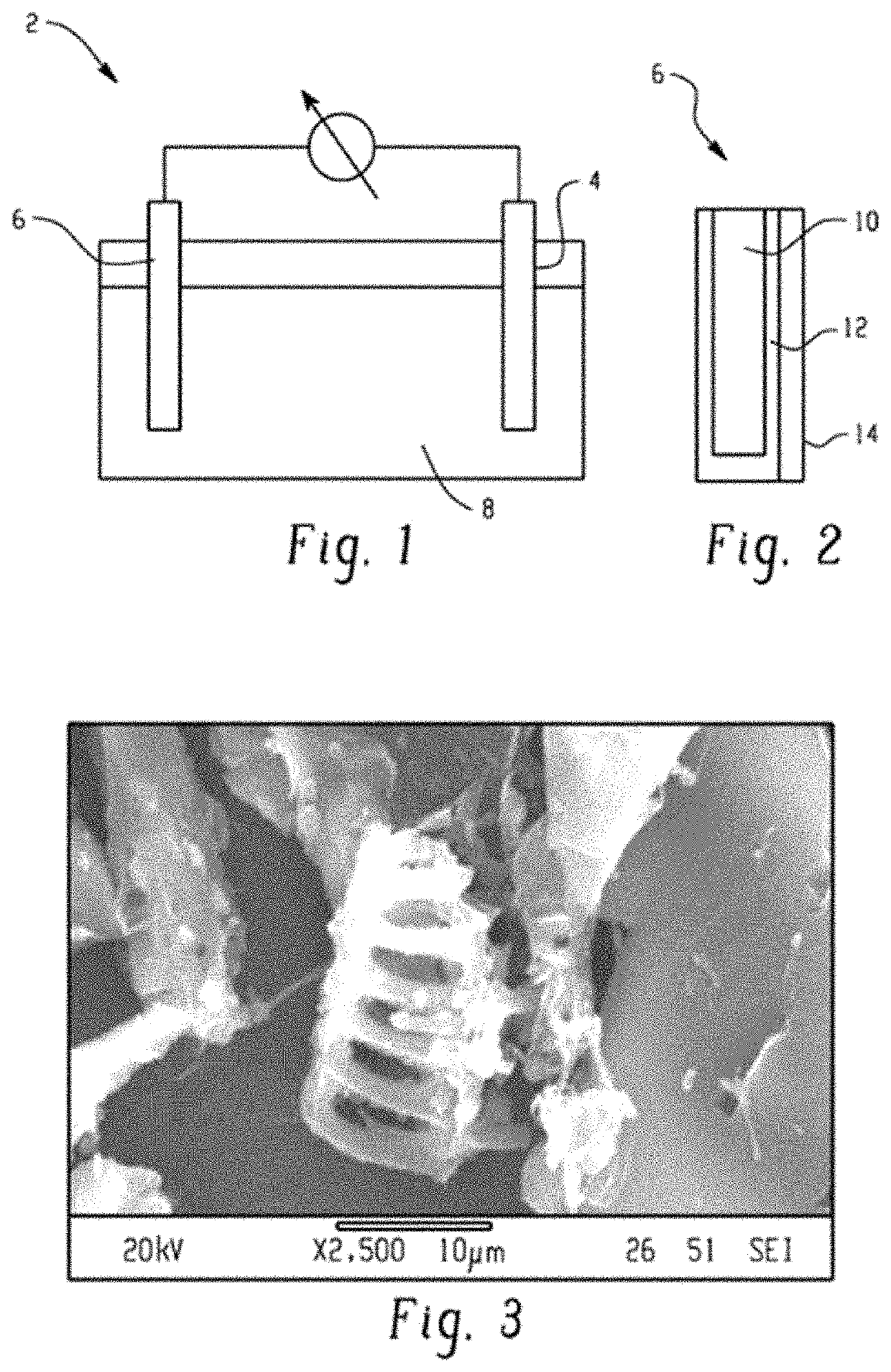
[0053]A porous activated carbon (AC)-PVDF anode was prepared using a phase inversion technique using water as the non-solvent. Specifically, 1 gram of PVDF was dissolved in 42.5 grams of acetone to form a 20% solution by mass using a rotor-stator mixer at room temperature (about 23 degrees Celsius (° C.)). It is noted that other mixing devices are considered as well, for example, FlackTek planetary mixers. 19 grams of activated carbon was added to the PVDF mixture. Portions of the solvent mixture were injected into 25 milliliters of water by rapidly squirting the solvent mixture into the water via a pipette and filtering the precipitate until all of the solvent mixture was precipitated. The water was being actively mixed via a stir bar during the injecting. During the phase inversion process acetone quickly diffused out from the AC-PVDF mixture and formed a macroporous AC-PVDF material, where the PVDF fibrillated in th...
example 2
Porosity on the Discharge Capacity
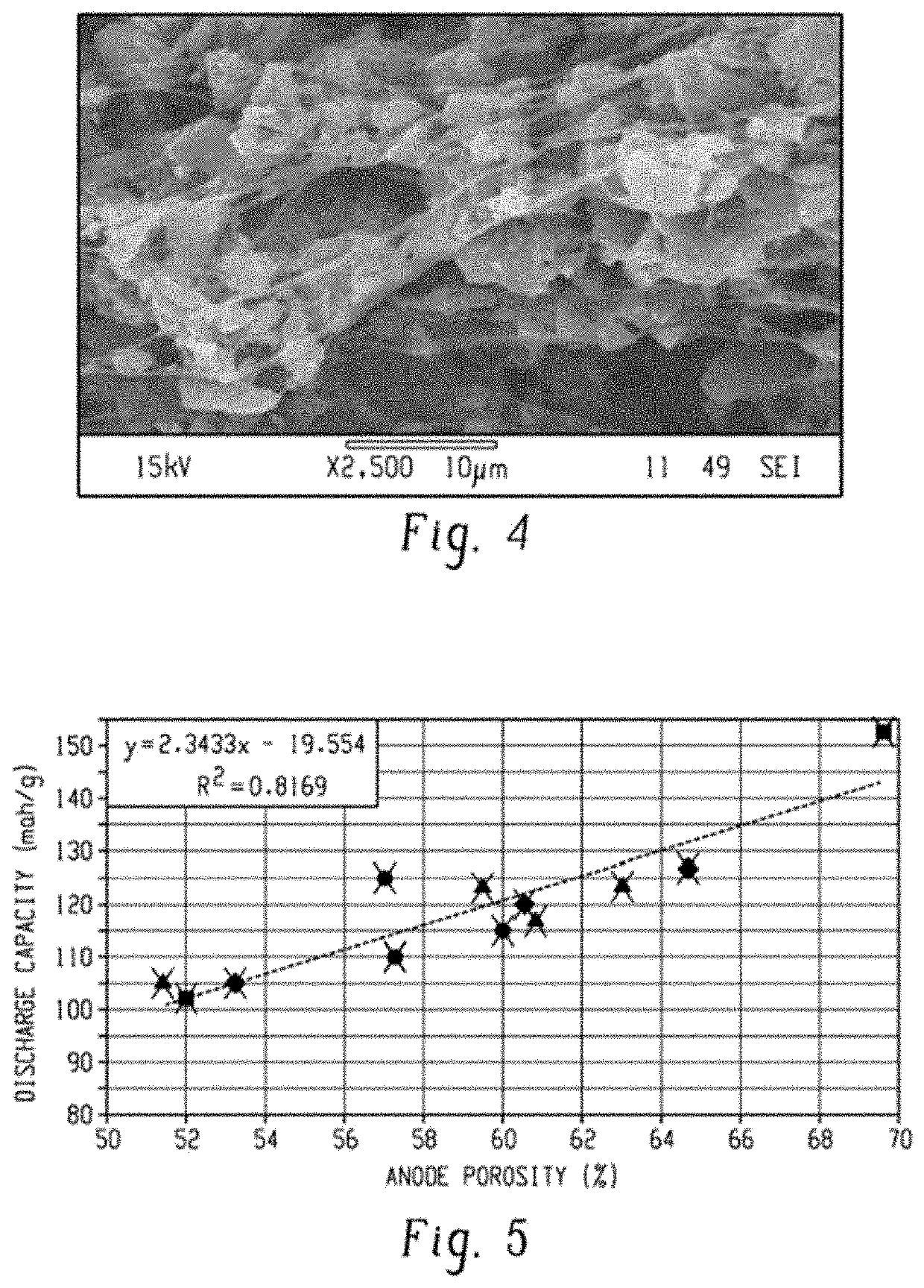
[0056]Twelve activated carbon anodes were prepared using the phase inversion method with varying concentration of the PVDF and activated carbon. The porosities and discharge capacities of the activated carbon anodes were determined and the results are illustrated in FIG. 5. In FIG. 5, the samples represented with the diamonds contained 9 wt % of fibrillated poly(vinylidene fluoride) and 91 wt % of the activated carbon; the samples represented with the circles contained 7 wt % of fibrillated poly(vinylidene fluoride) and 93 wt % of the activated carbon; and the samples represented by the triangles contained 5 wt % of fibrillated poly(vinylidene fluoride) and 95 wt % of the activated carbon; and the sample represented by the square illustrates that a porosity of almost 70 volume percent was capable of being prepared. FIG. 5 illustrates that increasing the activated carbon anode porosity resulted in an increase in the discharge capacity.
[0057]The disch...
examples 3-6
rbon Electrodes Formed by Other Methods
[0058]The layer of Example 3 was formed by mixing PVDF in acetone using an ultrasonic mixer. Activated carbon was added to the solution and mixed to form a solvent mixture comprising having a weight ratio of the activated carbon to the PVDF of 90:10. The solvent mixture was cast onto a polyester film using a drawdown bar with a gap height of 3 to 4 millimeters. The mixture was dried in air at room temperature and a 25 mm circular die was used to cut the sample and form the layer of Example 3. The layer of Example 3 produced a fractured, brittle sample that could not be tested.
[0059]The layer of Examples 4-6 was formed by mixing PVDF in acetone using an ultrasonic mixer. Activated carbon was added to the solution and mixed to form a solvent mixture comprising having a weight ratio of the activated carbon to the PVDF of 80:20 for Example 4, 90:10 for Example 5, and 95:5 for Example 6. The solvent mixture was put in a mold having a diameter of 25 ...
PUM
 Abstract
Description
Claims
Application Information