
Expandalbe anode assembly

an anode assembly and expandable technology, applied in the direction of paving details, protection foundations, constructions, etc., can solve the problems of steel reinforcement structure deterioration, steel reinforcement corrosion rate, concrete cracking, etc., to improve the electrolytic contact and connect quickly and efficiently

Active Publication Date: 2020-03-26
E CHEM TECH
View PDF0 Cites 0 Cited by
  • Summary
  • Abstract
  • Description
  • Claims
  • Application Information

AI Technical Summary

Benefits of technology

The present invention relates to an improved system for accommodating gaps in reinforced concrete structures, which can be easily installed and tailored to the size of the gap. The system includes an array of anode assemblies that can be inserted into the gap and expanded to bring the anodes into contact with the concrete surface. The anode assemblies can be connected together using an interconnecting conductor to create a discrete anode that can be used to protect steel in reinforced concrete. The system is efficient to install, flexible to accommodate variations in the size of the gap, and offers a more versatile way to protecting steel in reinforced concrete.

Problems solved by technology

Steel reinforced concrete structures are known to suffer from corrosion as a result of carbonation or chloride contamination in concrete.
This in turn leads to cracking of the concrete and accelerates the rate of corrosion of the steel reinforcement due to it becoming increasingly exposed to water and oxygen in the atmosphere.
Steel reinforcements present at the ends of adjacent concrete sections are particularly susceptible to corrosion since de-icing and marine salts are known to accumulate in the gaps formed between adjacent reinforced concrete sections.
However this is inhibited by the heavy steel reinforcement which must not be damaged by the formation of the hole.
However, since the gaps are relatively narrow, e.g. 15 to 200 mm, and are prone to movement, difficulties arise when trying to install sacrificial or impressed current anode systems on the concrete surface exposed in the gap.
A disadvantage of the inflatable assembly of GB2389591 is that contact between the anode and the concrete could be lost if the deformable material is damaged or corroded to an extent that the non-compressible fluid is caused to leak from the cavity.
Other anode assemblies are disclosed in GB2389591 but these have to be forcibly inserted into the gap defined by opposing reinforced concrete sections and therefore there is an increased risk of these anode assemblies becoming damaged during the installation procedure.
A further disadvantage of the anode assemblies disclosed in GB2389591 is that the deformable materials are susceptible to attack by contaminants such as engine oil and some tar products present on the roads.
This will limit the working lifetime of the anode assemblies and their ability to protect the steel reinforcements over extended periods of time.
Another disadvantage of the anode assemblies disclosed in GB2389591 is that gaps vary in size and the anode assemblies have to be made to fit a specific gap.

Method used


Image

  • Expandalbe anode assembly
  • Expandalbe anode assembly
  • Expandalbe anode assembly

Examples


example 1

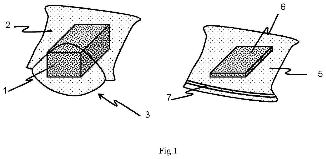
[0056]The expanding component of the anode assembly was constructed using blocks of foam 1, a vacuum packing machine (not shown) and vacuum pouches 2. The foam block 1 was polyurethane upholstery foam with a density of about 50 kg / m3. The foam 1 was resilient as opposed to a memory foam and measured about 185×105×47 mm.

[0057]The pouch 2 measured 300×200 mm when stored flat and was made of a clear (see through) plastic. In particular, the pouch 2 is made from a polyamide air impenetrable exterior and a polyethylene interior. The vacuum pouches 2 and vacuum packing machine were obtained from “lava vacuum packing”, and were manufactured in Germany by Manfred Landig. The vacuum packing machine used was the LAVA V.100 Classic vacuum Sealer.

[0058]Each foam block 1 was placed inside the vacuum pouch 2 which in turn was placed on a flat surface next to the vacuum packing machine. An A4 sized book weighing about 1 kg was placed on top of the pouch 2 and foam 1 to keep the pouch 2 flat as air...

example 2

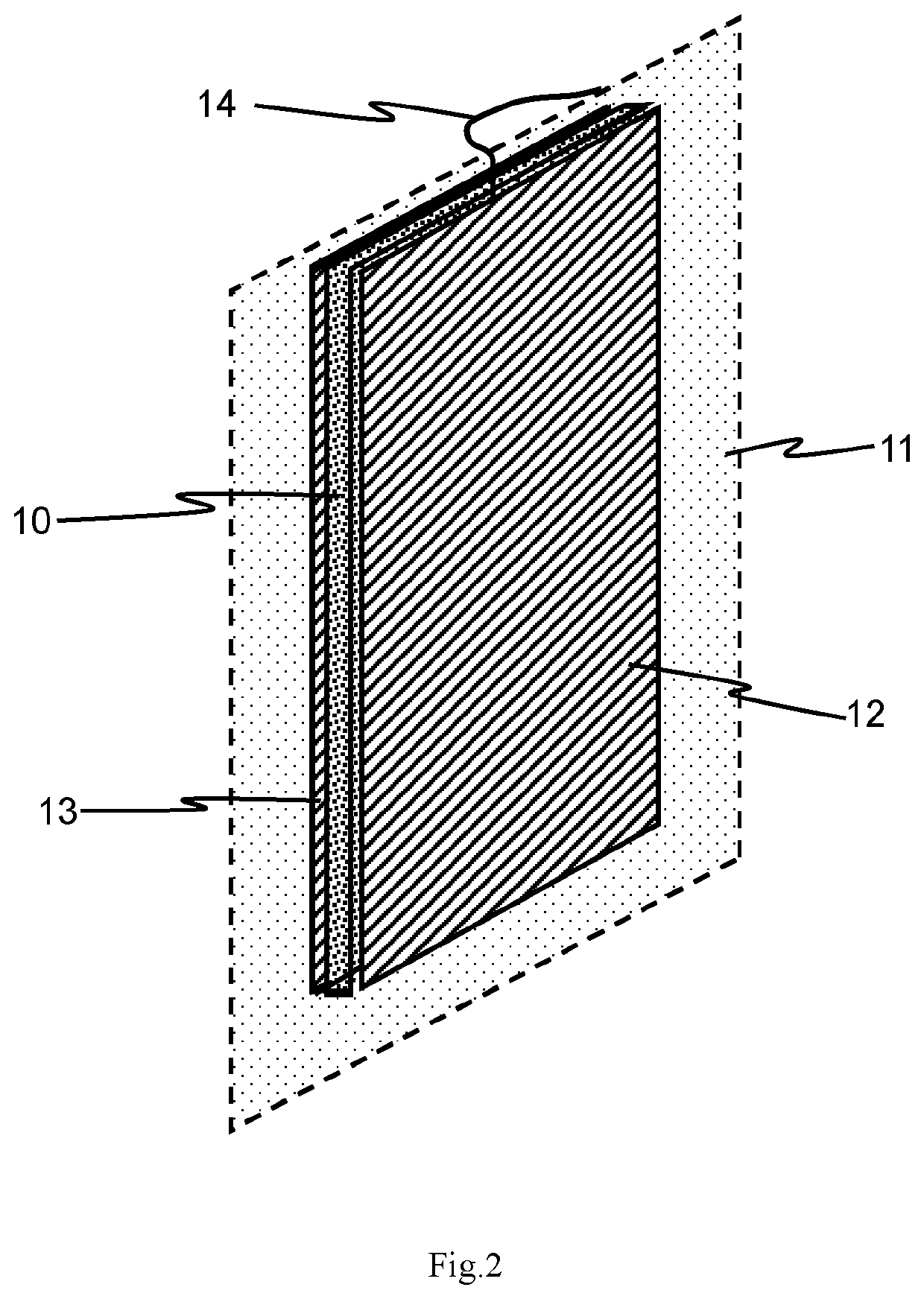
[0062]A single anode assembly 22 according to the present invention is best shown in FIG. 2. The assembly comprises a compressed foam 10, an evacuated vacuum pouch 11, a sheet of zinc 12 attached to an outer surface of the evacuated vacuum pouch 11, an adhesive (not shown), optionally a second sheet of zinc 13 and an electrical connector 14.

[0063]The compressed foam block 10 inside the sealed evacuated vacuum pouch 11 was prepared as described in Example 1. The foam block measured 185×105×47 mm before compression. The zinc plate 12, 13 was obtained from a zinc sheet supplier and was cut to a size of 105×185 mm. It was about 0.5 mm thick and weighed 130 grams.

[0064]The zinc plate, 12, 13 was prepared for use as an anode by soldering a copper core electric cable to the back of the plate 12, 13 and connecting it to a plastic coated titanium wire. The connection 14 was insulated with the exception of a short length of titanium that protruded just beyond the anode surface. This formed th...

example 3

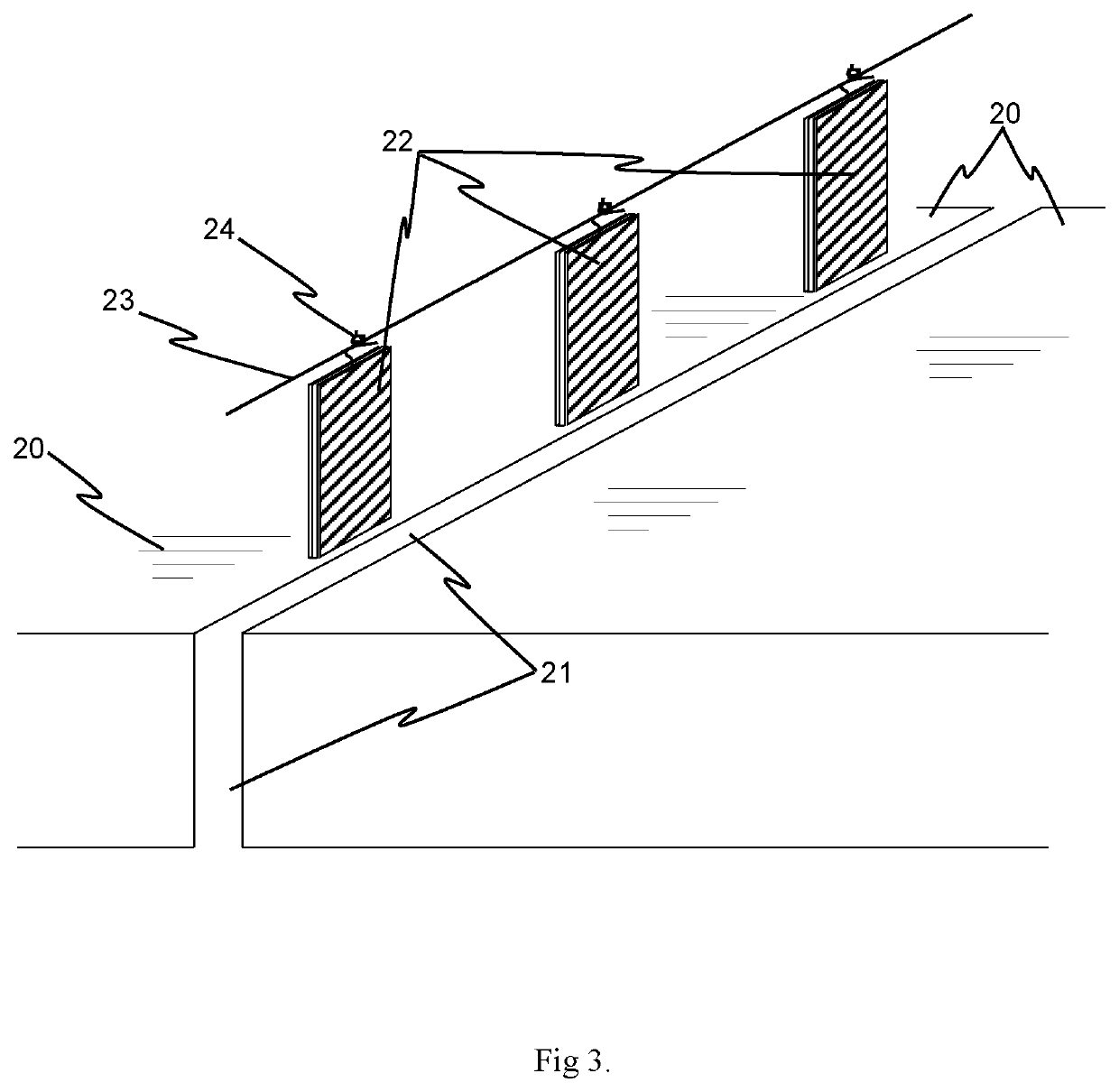
[0066]FIG. 3 shows an array of anode assemblies 22 installed in a gap 21 between reinforced concrete elements 20. To install the anode assemblies 22, the gap 21 at the joint between the concrete elements is cleared of debris to prepare it to receive the anode assemblies 22. The assemblies 22 are then prepared for insertion into the gap 21. This may include removing any external packaging and / or applying a thin layer of bedding material over the surface of the anode 12, 13 of the assembly 22 to facilitate electrolytic contact with the surface of the reinforced concrete elements 20. In this embodiment the bedding material was lime putty.

[0067]The anode assemblies 22 are then inserted into the gap 21 and arranged so that the assembly connectors 24 are exposed at the edge of the gap 21. The evacuated pouches 11 of the anode assembly 22 are then punctured (the seal is broken) to allow the assembly to expand and press the anode(s) 12, 13 of the assembly 22 against the surface(s) of the re...


PUM

PropertyMeasurementUnit
densityaaaaaaaaaa
thicknessaaaaaaaaaa
densityaaaaaaaaaa

Abstract

An array of anode assemblies for insertion at a plurality of locations in a gap between a section of a reinforced concrete structure and another solid structure is provided. Each anode assembly comprises an expandable member, an anode attached to the expandable member for protecting a steel reinforcement in the reinforced concrete structure, and an anode connector for interconnecting the array of anode assemblies. During use, each anode assembly of the array of anode assemblies is inserted into the gap, between the section of the reinforced concrete structure and the solid structure, at the plurality of locations. The expandable member of each anode assembly is configured to expand so as to press the anode into contact with a surface of the reinforced concrete structure.

Description

TECHNICAL FIELD OF THE INVENTION[0001]The present invention relates to an expandable anode assembly for protecting reinforcement in a reinforced concrete structure and in particular an array of anode assemblies suitable for insertion at a plurality of locations in a gap between a section of a reinforced concrete structure and another solid structure.[0002]The invention also relates to a method of producing an anode assembly and to a method of protecting a reinforcement in a reinforced concrete structure using said anode assembly, in particular said array of anode assemblies.BACKGROUND TO THE INVENTION[0003]Reinforced concrete is a composite material in which a reinforcement, typically of a metal such as steel, is used to counteract concrete's relatively low tensile strength and ductility. Steel reinforced concrete structures are known to suffer from corrosion as a result of carbonation or chloride contamination in concrete. When the steel reinforcement corrodes it produces by-produc...

Claims


Application Information

Patent Timeline
Patent Type & Authority Applications(United States)
IPC IPC(8): C23F13/18C23F13/20C23F13/14E01C11/04E01D19/06E02D31/06
CPCE01D19/06E02D31/06C23F13/18E01C11/04C23F13/14C23F2201/02C23F13/20C23F13/06E01C11/10
Inventor GLASSGLASS, STEPHENROBERTSDAVISON, NIGEL
Owner E CHEM TECH
Learn More