Object classification system and method

a classification system and object technology, applied in the field of optical wavebased computing, can solve the problems of limiting the complexity of tasks that can be performed, limiting the complexity of the proposed implementation, and most of the processing still happens, so as to improve the signal mixing properties of the mixing unit, reduce the complexity of the overall system, and improve the effect of memory

Active Publication Date: 2020-04-23
UNIV GENT +1
View PDF0 Cites 3 Cited by
  • Summary
  • Abstract
  • Description
  • Claims
  • Application Information

AI Technical Summary

Benefits of technology

[0079]A cavity 12 is designed and optimized as the mixing unit 1 of the passive photonics wave-based computing system so that good mixing of the inputs is achieved, e.g. through an effective randomization of the propagating wave direction inside the cavity 12 after a large number of reflections 13. The cavity shape typically displays curved features, for example the arc of a quarter-stadium cavity, but many other cavity shapes may be considered as mixing unit too. In a particular example, a quarter-stadium design may display 30 μm and 15 μm long semi-axis, however these numbers can vary according to a particular task to be solved and the required speed of the input signals. It is an advantage of the present invention to show low losses under the mixing procedure which is achieved by the multiple reflections 13 off the reflective cavity walls 11 before being partially transferred into one or more outputs 14. High reflectivity from the enclosing boundary 11 walls of the cavity may be obtained by the use of a photonic crystal structure comprising a regular lattice of air holes in silicon, but is not limited thereto and other material interfaces of the cavity walls may be conceived. Propagation losses, scattering losses, surface losses, and other sources of imperfections in the material and fabrication are typically small compared to the coupling losses induced by the plurality of input and output ports 10 connected to the cavity. Hence the number of input and output connectors 10 constitutes the major control variable of the cavity's quality factor (Q-factor). The Q-factor is related to the lifetime of a cavity 12 excitation through one or more of its input connectors 10; the final decay of any excitation through loss mechanisms provides a form of fading memory to the passive photonic computing system. A reasonable minimum number of input and output connectors to perform computational tasks with low error rates is typically ranging between five and nine, corresponding to Q-factors between 3000 and 5000, but different choices may lead to better results in some cases. A higher Q-factor can be obtained by reducing the number of input and output connectors which gives rise to better system memory but trades system bandwidth.
[0080]It is of advantage of the described embodiment that the input connectors 10 can serve as output connectors at the same time, thus limiting the complexity of the overall system. Furthermore, the input or output connectors 10 typically comprise of an adiabatically controlled taper 101 connecting to the external input or output waveguides and a defect waveguide 102 inside the photonic crystal structure, both ensuring that input and output radiation signals are delivered to and coupled out from the cavity 12. The tapered sections 101 can be tailored to inject or extract a given fraction of the incident radiation signal, hence are another means to control the cavity's Q-factor. Typical transmissivity values range from 30% to 95%, but can be adapted accordingly and on an individual basis. Moreover it is possible, although not required to add delay lines to the input or output connectors 10 in order to provide for increased memory and better signal mixing properties of the mixing unit 1.
[0081]Furthermore, an embodiment of the present invention may benefit from the flat surface structure of the cavity 12 which is ideally suited for deposition of thin film coatings, e.g. ferroelectric thin films but not limited thereto. In a likely manner, a cavity region 12 based on air surrounded by photonic crystal walls made from silicon rods is an embodiment of the present invention that could be filled with a nonlinear material, nonlinear polymers for instance. Another possibility is to pattern the cavity 12 into a III-IV material. All the mentioned optional features provide an enhanced nonlinear response to the mixing unit 1 which may lead to increased efficiency or computational power of the passive photonic computing system.
[0082]It may be an advantage of the present invention to stack several mixing 1 units together or to combine them into a hierarchical architecture which may allow for a more efficient allocation of computing resources, faster problem solving, or the treatment of derived high-level features.
[0083]By way of illustration, further features and characteristics will be described with reference to FIG. 1. The particular quarter-stadium shape shown typically shows interesting dynamics and results in complete mixing of the fields, in the sense that an input wave will obtain all possible wave-vectors in the cavity. The mixing unit behaves like a fading memory necessary for wave-based computing.
[0084]With respect to its operating, in order to perform operations at a certain bitrate, the lifetime of the cavity should be a least larger than the bit period. Apart from optimising Q-factor and waveguide coupling, we can also simply increase the size of the cavity if we want to process signals with a lower bitrate. This is a valid option, since the propagation losses are small compared to the scattering and coupling losses.

Problems solved by technology

However, most of this processing still happens in software on power-hungry computers.
However, the proposed implementation suffers from fundamental scaling limits coming from the 3 dB loss associated with the sequence of combiners used in the system.
Nevertheless, the complexity of tasks the reservoir can perform depends on the number of neurons it consists of, these losses also limit the complexity of tasks that can be performed, and consequently there is still room for improvement.

Method used


Image

  • Object classification system and method
  • Object classification system and method
  • Object classification system and method

Examples


example 1

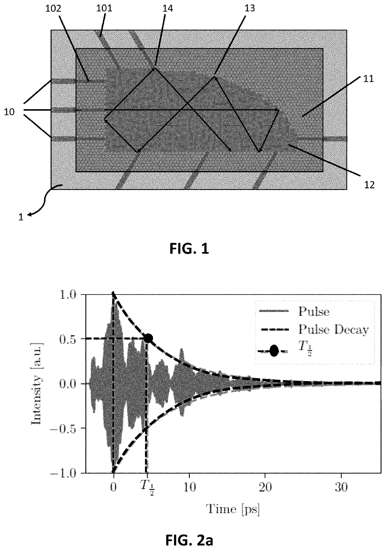
[0104]In the first example, benchmarking of the wave-based computing system as shown in FIG. 1 is discussed.

[0105]A first benchmark for the memory of the signal is the ability to reproduce the exact input with a certain amount of delay. From FIG. 7, for the current design, there is quite a wide basin of operation. Using 5 outputs results in being able to reproduce the input with a larger delay, which makes sense because of the increased Q factor and thus memory for 5 outputs.

[0106]A second benchmark which illustrates the ability to perform Boolean operations is the nonlinear xor task, where the xor is taken between two bits bn and bn-k, k bits apart. Since a normal conventional linear classifier can only achieve a minimum of 25% error rate, it is also a good performance indicator of the nonlinearity in the system.

[0107]First, the performance of an xor on two neighboring bits was assessed, while continuously increasing the bit separation. We call this the xor-specific memory of the r...

example 2

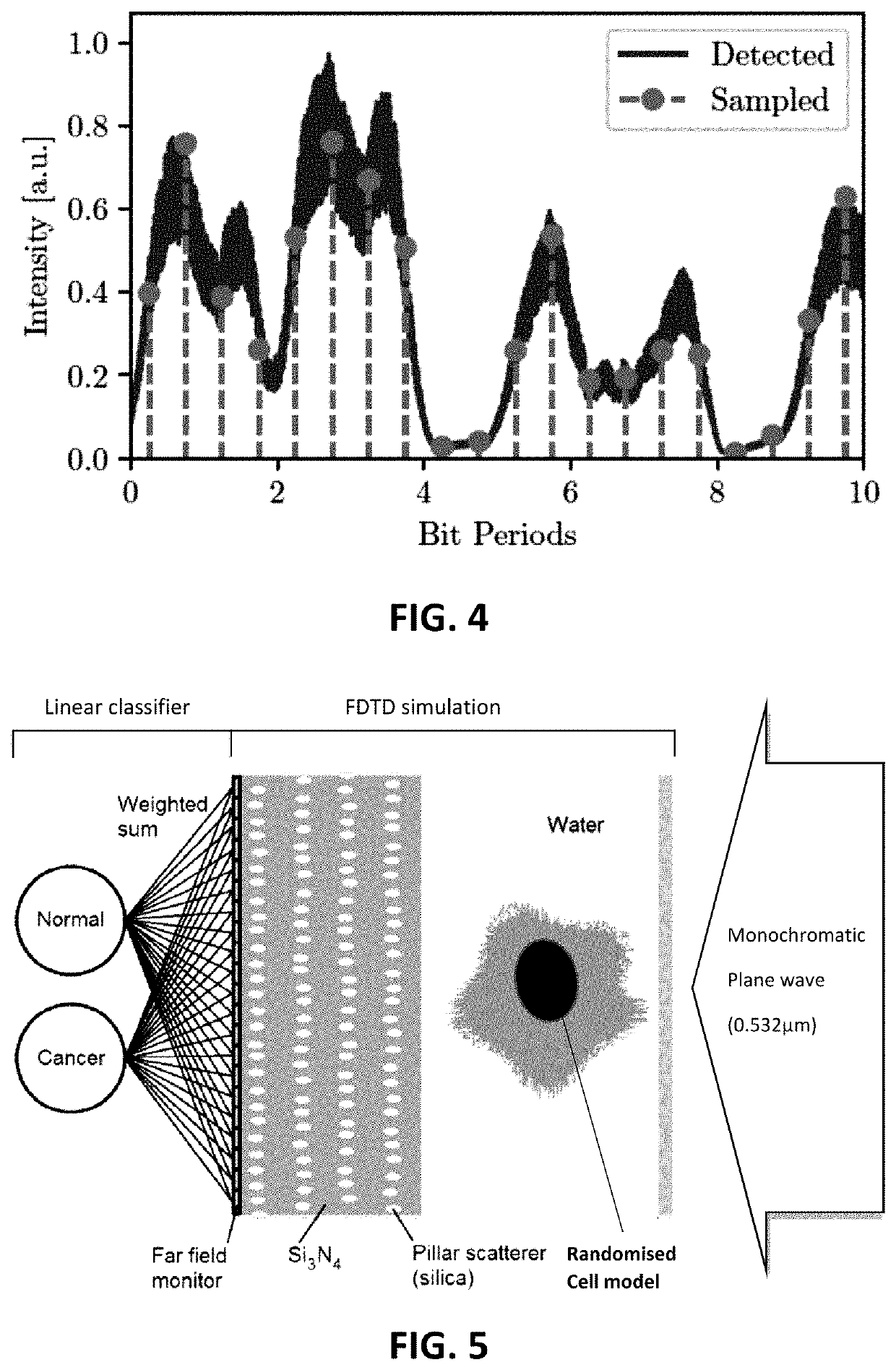
[0112]In the second example, the simple passive photonic chip containing a collection of silica pillar scatterers embedded in silicon nitride as shown in FIG. 5 is used as interface between a biological cell hologram projection and a line-scan image sensor, in order to simplify and speed up a machine learning processing on the acquired image. In particular, the classification of cells of different nucleus sizes flowing along a microfluidic channel equipped with a digital holographic microscope was simulated through 2D FDTD simulations. The scatterers are employed to better exploit the nonlinear relation that links the cell refractive index structure (and the corresponding phase shift exerted on the impinging light) with the radiation intensity collected by the sensor. In this way, the complexity of a nonlinear stage can be controlled in order to increase the performances of a linear classifier that acts on the output of the sensor pixels. The proposed implementation illustrates that...


PUM

PropertyMeasurementUnit
wavelengthaaaaaaaaaa
half lifeaaaaaaaaaa
half life timeaaaaaaaaaa

Abstract

An object classification system for classifying objects is described. The system comprises an imaging region adapted for irradiating an object of interest, an arrayed detector, and a mixing unit configured for mixing the irradiation stemming from the object of interest by reflecting or scattering on average at least three times the irradiation after its interaction with the object of interest and prior to said detection.

Description

FIELD OF THE INVENTION[0001]The invention relates to the field of optical wave-based computing. More specifically it relates to methods and systems for optical wave-based computing with low loss using a mixing unit.BACKGROUND OF THE INVENTION[0002]The more we get swamped by Big Data, the more we let computers take over the data processing. Machine Learning is therefore currently one of the fastest growing disciplines in computer science and statistics. However, most of this processing still happens in software on power-hungry computers.[0003]An alternative hardware implementation is a so-called Reservoir Computer specifically designed for efficient optical computation. Reservoir Computing is a machine learning branch focusing on processing of time-dependent data. It was first proposed in the early 2000s as a way of using an untrained neural network with internal feedback combined with a trained linear readout layer to perform classification of temporal data. The feedback through the...

Claims


Application Information

Patent Timeline
Patent Type & Authority Applications(United States)
IPC IPC(8): G06K9/00G06K9/20H04N5/335G01N21/47G01N33/48
CPCG01N2201/06113G06K9/2036G01N21/47G01N33/48G01N2201/10H04N5/335G06K9/00147G06K9/00134G06N3/0675G02B6/1225G02B6/1228G06V20/698G06V20/693H04N25/00
Inventor BIENSTMAN, PETERLUGNAN, ALESSIOLAPORTE, FLORIS
Owner UNIV GENT
Why Eureka
Try Eureka