Eureka AIR delivers breakthrough ideas for toughest innovation challenges, trusted by R&D personnel around the world.

Attaching an SMD to an insulating layer with a solder joint in a cavity formed in an insulating layer

a technology of insulating layer and solder joint, which is applied in the field of surface mount components, can solve the problems of premature removal of printed circuit boards, limited standoff, and damage of smd, and achieve the effects of increasing the associated standoff, simple operation, and increasing the service life of components

Active Publication Date: 2020-07-02
SAFRAN ELECTRONICS & DEFENSE
View PDF0 Cites 0 Cited by
  • Summary
  • Abstract
  • Description
  • Claims
  • Application Information

AI Technical Summary

Benefits of technology

The invention proposes a new way to attach a component to a printed circuit board that improves its longevity by increasing the space between the component and the circuit board. This process is simple, cost-effective, and doesn't impact the efficiency of assembly, regardless of the component's density or type.

Problems solved by technology

However, the increase in the standoff is limited by the usual means of assembly available in production and by the diversity of geometries of the component housings to be surface soldered.
However, the SMD can be damaged if it expands in a Z-shape (i.e. in a direction normal to the surface of the printed circuit board on which the SMD is soldered) and detaches prematurely from the printed circuit board.
Furthermore, this solution is not applicable to all types of SMDs, regardless of their size, weight and the type of termination they carry.
However, this remains limited by the volume of solder paste that can be introduced into the screen openings for demoulding and to limit the coalescence of the solder paste without generating microbeads.
However, these variable thicknesses often involve screen printing problems for adjacent SMDs (unsatisfactory solder paste height in adjacent holes) and make it difficult to optimize the SMD layout in the circuit board.
Finally, depositing the solder paste by screen printing limits the implantation density of the electronic components on the printed circuit board and / or the type of component that can be used, especially in the case of fine pitch components.

Method used


Image

  • Attaching an SMD to an insulating layer with a solder joint in a cavity formed in an insulating layer
  • Attaching an SMD to an insulating layer with a solder joint in a cavity formed in an insulating layer
  • Attaching an SMD to an insulating layer with a solder joint in a cavity formed in an insulating layer

Examples


first embodiment

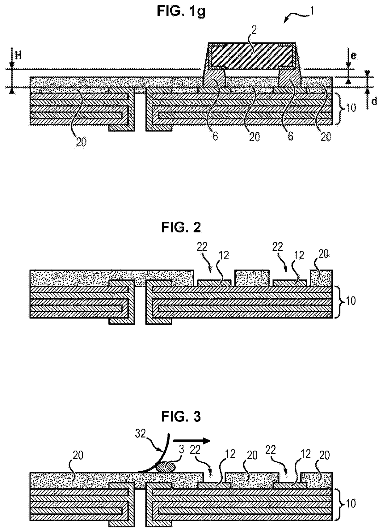
[0069]In a first embodiment, the insulating layer 20 can be applied by surface photolithography. In this case, the cavities 22 can also be formed by surface photolithography (see FIG. 2).

[0070]For this purpose, in a first step, a photoresist for forming the insulating layer 20 is applied to the connecting surface 14 in the form of a film. The resin can be a negative resin (ultraviolet radiation causes polymerization of the exposed areas, giving these areas a particular resistance to the developing solvent, while the noninsolated parts selectively disappear in this solvent) or a positive resin (ultraviolet radiation causes the macromolecules to break down, resulting in increased solubility of the exposed areas in the developing solvent). The resin may include an epoxy resin.

[0071]In a second step, a mask is applied to the resin film. The mask includes transparent and opaque areas to form the cavities 22 and the insulating layer 20.

[0072]In a third step, the resin film is exposed to l...

second embodiment

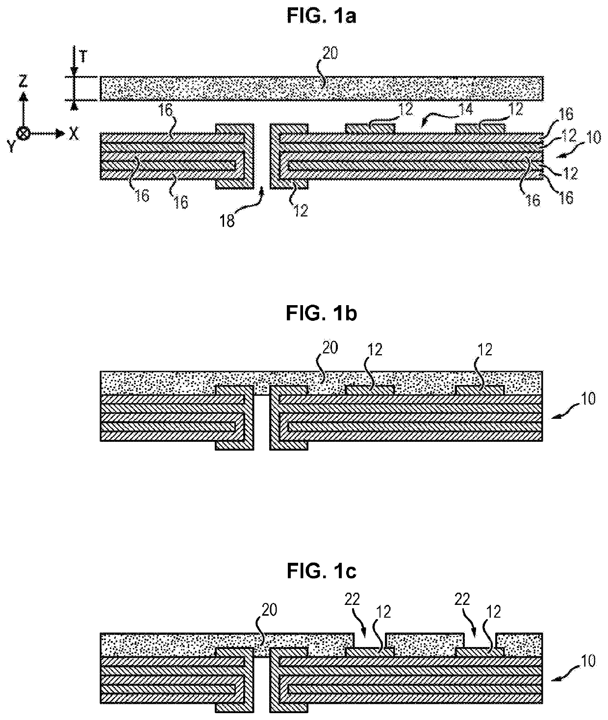
[0075]In a second embodiment, the insulating layer 20 can be applied and attached to the connecting surface 14, for example by lamination or gluing with an adhesive layer (see FIGS. 1a and 1b). The adhesive layer can include any type of adhesive material conventionally used in the printed circuit board industry to bond layers together, typically an epoxy adhesive.

[0076]The cavities 22 can then be preformed in the insulating layer 20 before it is placed on the connecting surface 14, or after it has been attached (as in FIG. 1c for example).

[0077]For example, the cavities 22 can be formed by cutting out insulating layer 20. Cutting can be done mechanically (using a cutting tool such as mechanical milling or mechanical drilling or laser drilling before placing on the surface 14). In the case of application on the surface 14 before the cavities are made, the cutting can be done by chemistry on dry or liquid photoimageable films or by mechanical milling or laser drilling. Laser drilling ...


PUM


Abstract

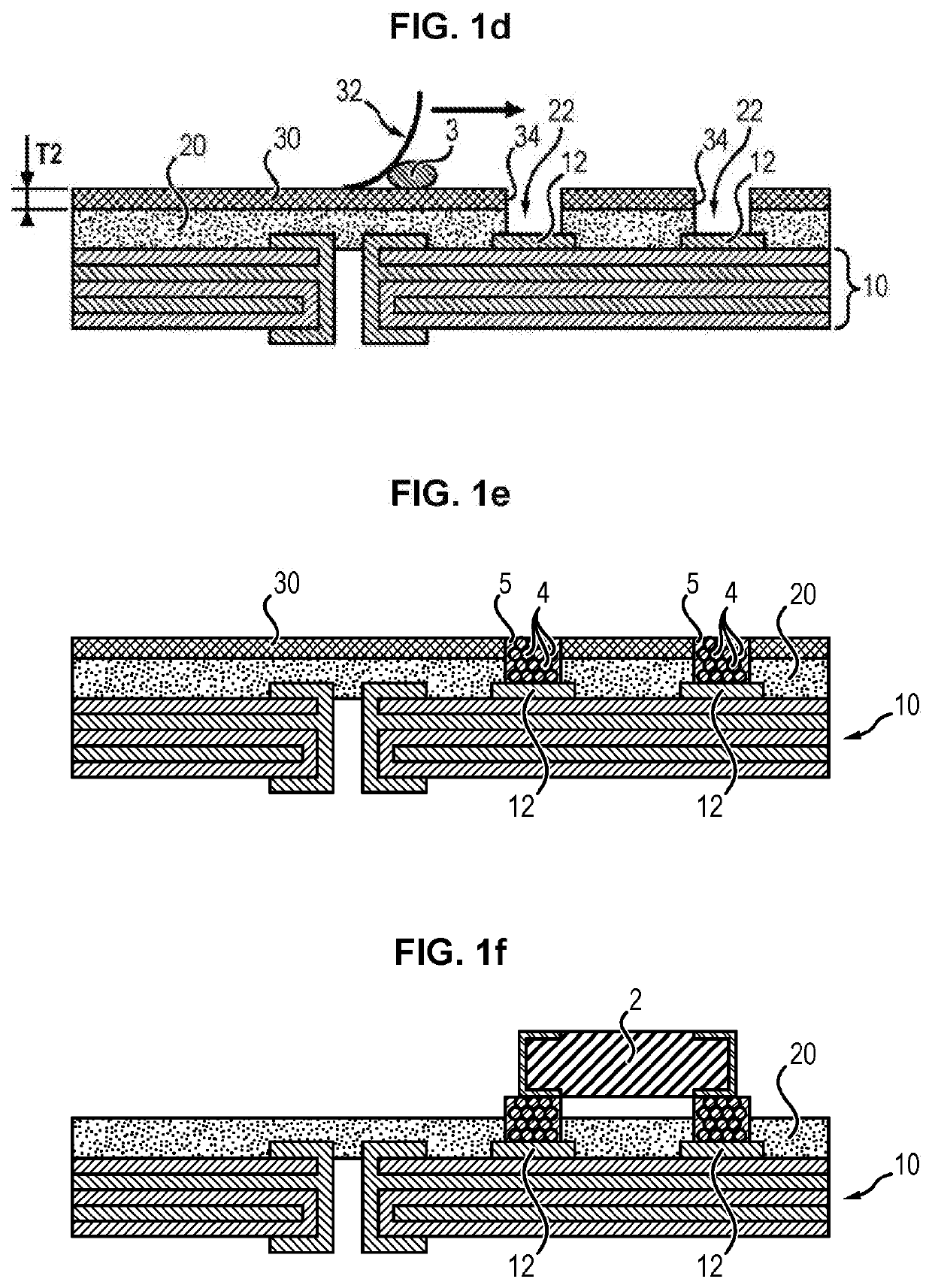
The invention relates to a method (S) for attaching an SMD to a printed circuit (10), comprising the following steps: —applying an insulating layer (20) (S1) onto the printed circuit (10), —forming a cavity (22) in the insulating layer (20) above the conductive layer (12) (S2) of the printed circuit, —filling the cavity (22) with a solder paste (3), —positioning the SMD over the cavity (22) (S4), and —applying a heat treatment (S5) to the printed circuit (10).

Description

FIELD OF THE INVENTION[0001]The invention relates to the field of circuit boards, notably in the field of aeronautics and space, and more precisely to the attachment of surface mount components on printed circuits.TECHNOLOGICAL BACKGROUND[0002]In a manner known per se, a circuit board can comprise surface mount devices (SMDs), i.e. electronic components soldered directly to the surface of a printed circuit board.[0003]Usually, SMDs are soldered on the surface either by reflow soldering or wave soldering.[0004]In the case of reflow soldering, the bare printed circuit board is first screenprinted by covering the conductive layers of the printed circuit board (usually copper) with a solder paste using a screenprinting screen (or stencil) so that only the locations intended to receive the component terminations are covered by the solder paste. Solder paste comprises, in a manner known per se, a metal alloy suspended in a soldering flux. Then, the terminations of the components (SMDs) ar...

Claims


Application Information

Patent Timeline
Patent Type & Authority Applications(United States)
IPC IPC(8): H05K3/34B23K3/06H05K3/12
CPCH05K2203/043B23K2101/40H05K3/3452H05K3/1216B23K3/0607H05K3/3442H05K2203/0568H05K2203/0577H05K3/3485
Inventor LECORDIER, DENISCHOCTEAU, PHILIPPEJOUAN, JACKY
Owner SAFRAN ELECTRONICS & DEFENSE
Why Eureka
Eureka Blog
Learn More