
Filtration membrane and methods of use and manufacture thereof

Active Publication Date: 2020-11-12
VALORBEC PARTNERSHIP
View PDF0 Cites 3 Cited by
  • Summary
  • Abstract
  • Description
  • Claims
  • Application Information

AI Technical Summary

Benefits of technology

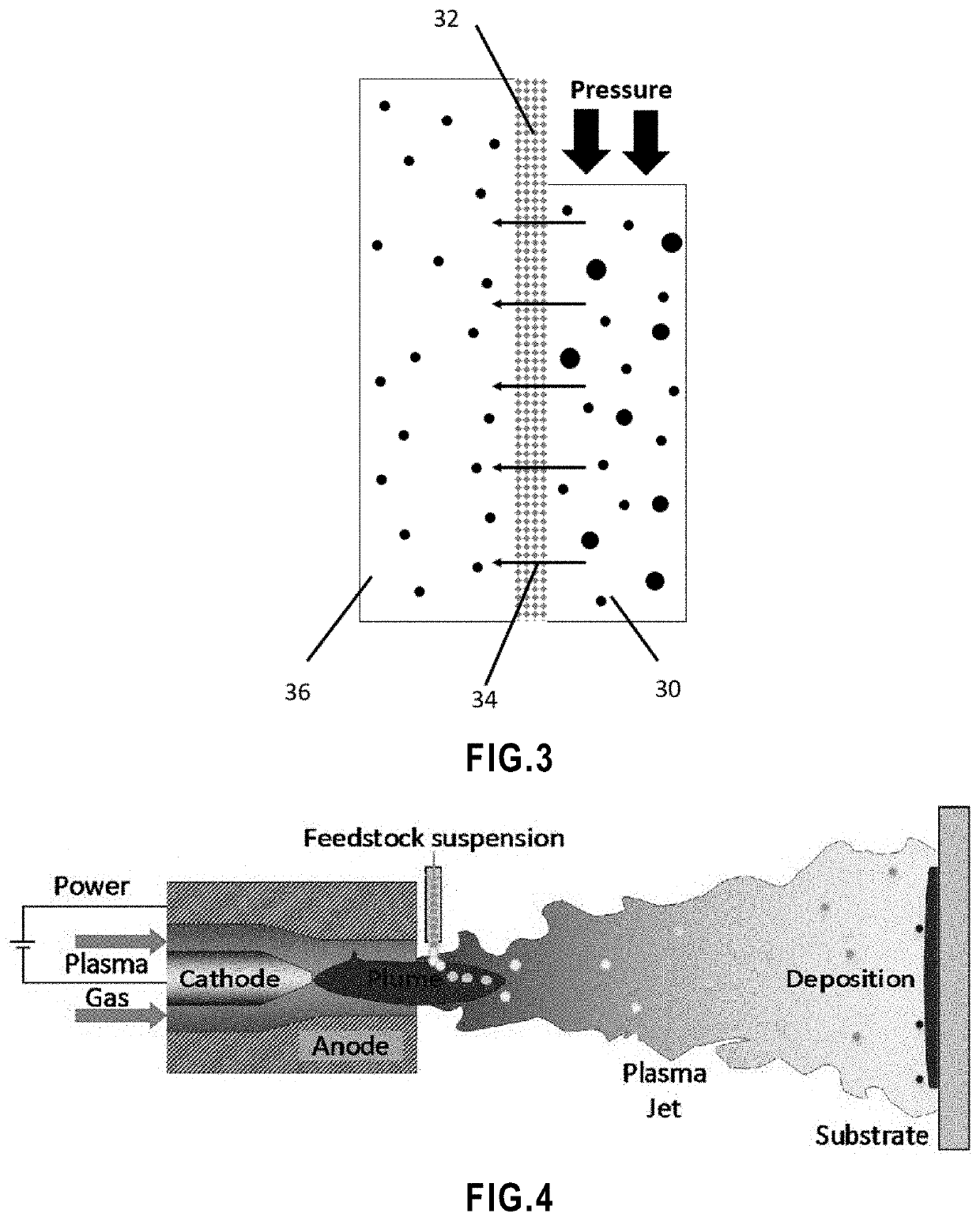
The present invention provides a filtration membrane with a porous support substrate and a porous active layer on top of the substrate. The active layer is made of a network of interconnected ceramic splats with ceramic particles occupying interstices between the splats. The membrane has a high porosity and a large surface area, making it suitable for various applications such as filtering, separating, and purifying materials. The membrane can also be made with anti-fouling photocatalytic properties and can be cleaned and degraded by UV radiation. The method of manufacturing the membrane involves providing a support substrate, suspending ceramic particles, and plasma spraying them onto the substrate to produce a porous active layer. The membrane can also be made with different suspensions of particles and can be cooled during the plasma spraying process.

Problems solved by technology

Beside the global water shortage, poor water quality in many parts of the world is the main cause for diseases such as cholera and diarrhea.
However, their application has been limited to those areas in which polymer membranes cannot be used, due to their higher price which has been made them unsuitable for large scale applications.
Polymer membranes are not reliable in aggressive acidic or basic environments, would dissolve in many solvents and cannot be used in temperatures over 100° C. Furthermore, ceramic membranes can be cleaned by back flush, by high temperature sterilization or by chemical agents and they do not swell or deform.
On the other hand, compared to polymer membranes, ceramic membranes are more expensive and sealing them in metallic housing is not easy.
In addition, they are brittle, much heavier and have lower packing density.
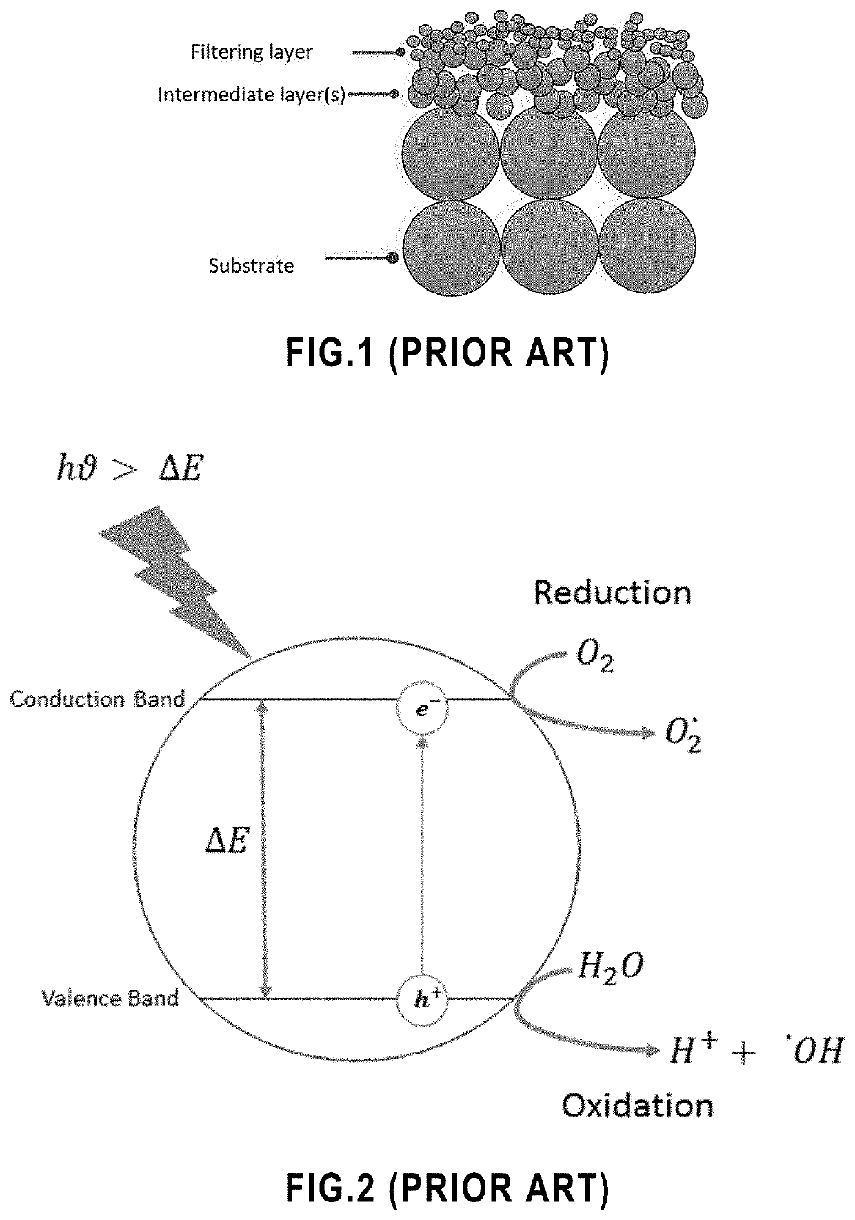
However, producing a defect free filtering layer is not easy with commercial manufacturing methods.
A too thick layer is more prone to crack during drying and sintering process and a too thin layer is more likely to form incompletely, thus not covering the whole surface of the substrate.
However, application of nanoparticles in ceramic membranes is not easy due to difficulty of immobilization of these particles on commercial ceramic membranes [17].
However, it has been shown that the sintering process drastically influences the pore size of the membrane.
The above manufacturing methods include several production steps resulting in the process to be time consuming and expensive.
Furthermore, they require a high temperature heat treatment step at the end, which is an energy consuming process and can take a long time to complete.
In addition, in the case of using metallic porous substrates, the sintering process may result in densification of the substrate and its oxidation.
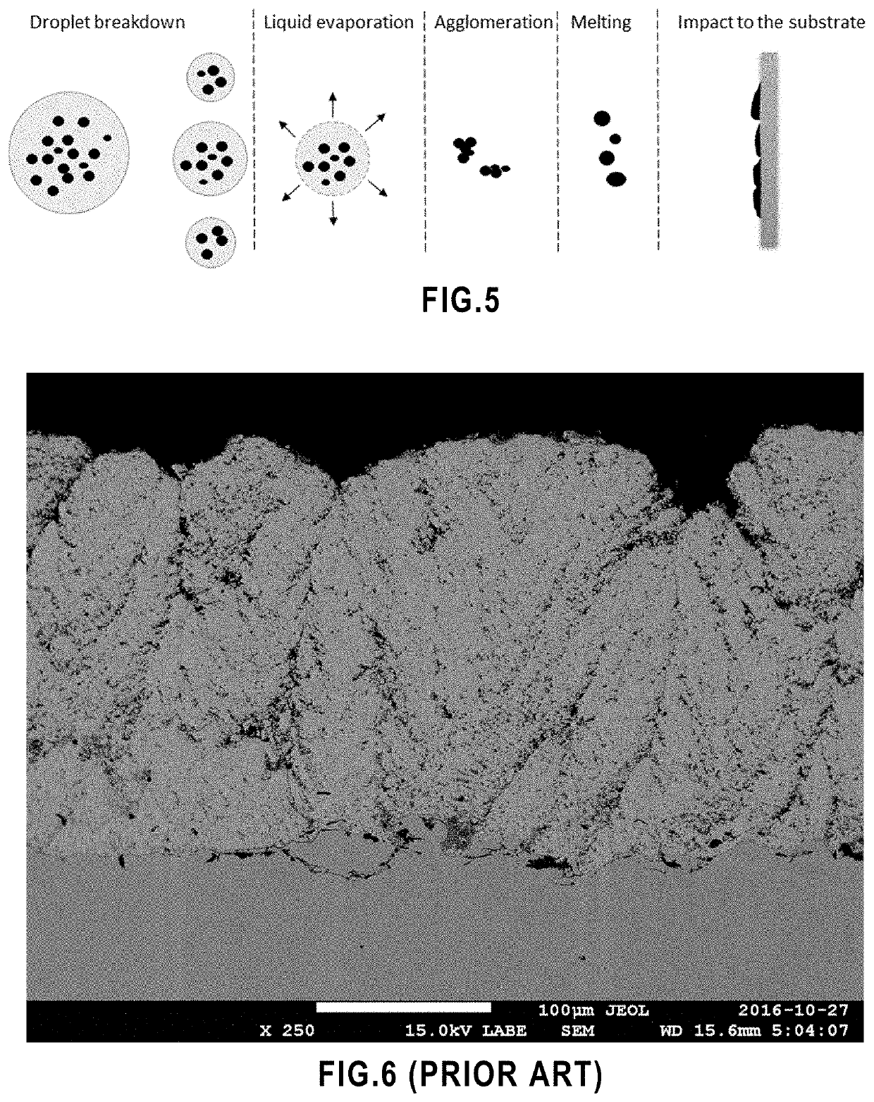
On the other hand, the microstructures of these coatings may contain features such as intra-lamellar cracks, macro pores, inter-lamellar cracks, which might be considered as defects in some applications.
Small particles tend to form larger agglomerates due to electrostatic forces, which may lead to clogging the injecting system.
In addition, it is more difficult for the fine particles to penetrate the plasma jet.
As a result, spraying submicron sized particles with atmospheric plasma spray (APS) method requires a carrier gas flow rates as high as 80 slm, which greatly perturbs and intensively cools down the plasma jet.
Also, limitation in choosing the minimum particle size used in conventional plasma spray process imposes a limit on the minimum splat size and consequently on minimum thickness of the coating, since larger particles are deposited in the form of larger splats with higher thickness.
However, recovering the nano-catalyst particles is an issue and adds a post treatment step to the filtration process.
The drawback of immobilization of catalyst particles was the decrease in photodegradation activity due to the reduction of active surface area.
However, polymeric membranes are not stable under UV irradiation.

Method used


Image

  • Filtration membrane and methods of use and manufacture thereof
  • Filtration membrane and methods of use and manufacture thereof
  • Filtration membrane and methods of use and manufacture thereof

Examples


example 1

[0233]Below, we report below the fabrication of a ceramic filtration membrane by suspension plasma spraying (SPS). More specifically, we report:[0234]the development of a SPS titanium dioxide (SPS TiO2) membrane,[0235]the evaluation of the impact of different spray parameters and the optimization of some these parameters, and[0236]the characterization of the SPS TiO2 membrane and the evaluation of its performance.

[0237]A porous water permeable titanium dioxide membrane with 14% of open porosity and considerable water flux was produced. In this SPS TiO2 membrane, a network of open pores was generated by accumulation of un-melted and re-solidified particles. In addition, the SPS titanium dioxide membrane exhibited photocatalytic property.

[0238]The SPS TiO2 membrane was generated using sub-micron sized particles in suspension plasma spray, which brought interesting characteristics in terms of the smaller size of the droplets, which led to a membrane with smaller pore size and lower thi...

example 2

Optimization of the Membrane

[0358]The membranes of Example 1 were optimized in order to obtain a higher porosity resulting in a higher liquid flow rate. This was done by increasing the number of un-melted and / or re-solidified particles within the structure.

[0359]The TiO2 powder was 100% anatase. FIG. 42 shows the as purchased TiO2 powder (KS-203A / B, TKB Trading, US). The number-based average powder particle size was 125 nm. the volume-based particle size was D (50)=390 nm as shown in FIG. 43.

[0360]Twelve membranes were sprayed according to Table 13 and Table 14.

TABLE 13Constant spray conditions.TorchInjectorGasCurrentpowerVoltagespeeddiameterNo.of(LPM)(A)(kW)(V)(m / s)(mm)passAr / H2 (60 / 2)500255010.225

TABLE 14Matrix of experiments.SuspensionMembraneSolid contentflow rateSpray distanceno.(%)(mL / min)(mm)120305022030603203070420405052040606204070730305083030609303070103040501130406012304070

Increase of the Porosity

[0361]The porosity was increased from 14% in membrane no. 1 (SPS-W-6 in the ...


PUM

PropertyMeasurementUnit
Pore sizeaaaaaaaaaa
Pore sizeaaaaaaaaaa
Lengthaaaaaaaaaa

Abstract

A filtration membrane is provided. It comprises a porous support substrate and a porous active layer on top of the support substrate, wherein the active layer is formed of a network of interconnected, randomly arranged ceramic splats with ceramic particles occupying interstices between the splats, and wherein free spaces between the particles define a network of interconnected pores extending through the thickness of the active layer. There are also provided a method of filtering a feed using the membrane and a method of manufacturing the membrane by suspension plasma spraying.

Description

CROSS REFERENCE TO RELATED APPLICATIONS[0001]This application claims benefit, under 35 U.S.C. § 119(e), of U.S. provisional application Ser. No. 62 / 845,590, filed on May 3, 2019. All documents above are incorporated herein in their entirety by reference.FIELD OF THE INVENTION[0002]The present invention relates to filtration membranes. More specifically, the present invention is concerned with filtration membrane with an active layer with a unique microstructure.BACKGROUND OF THE INVENTIONLiquid Filtration Membranes[0003]Removing hazardous pollutants is a major concern of many industries such as chemical, petrochemical, mechanical, automotive, textile, pulp and paper, biotechnology, cosmetic, pharmaceutical and food and beverages. Filtration using membranes is known as an effective, sustainable, inexpensive and eco-friendly technique to remove contaminants. Water treatment is another major area, in which filtration plays an important role.[0004]During the last century, global water d...

Claims


Application Information

Patent Timeline
IPC IPC(8): B01D67/00B01D69/10B01D71/02B01D69/02C02F1/72C02F1/32B01D65/02B01D65/08B01D69/14
CPCC02F1/32B01D69/145C02F1/725B01D69/10C02F2303/16B01D65/02C02F2303/20B01D2325/02C02F2101/30B01D67/0039B01D65/08B01D69/02C02F2305/10B01D71/02B01D67/0041B01D69/12B01D71/024B01D2321/343B01D69/141B01D2311/2619B01D2323/18C02F1/444Y02W10/37B01D67/00414B01D71/0211B01D71/0213B01D69/108B01D69/107B01D67/00411B01D2325/0283B01D71/0271
Inventor ALE EBRAHIM, ELNAZSADATMOREAU, CHRISTIANDOLATABADI, ALIRAHAMAN, MD. SAIFURTARASI, FARIBA
Owner VALORBEC PARTNERSHIP
Learn More