Support frame for pellicles, pellicle, and method for manufacturing same

Active Publication Date: 2021-01-14
NIPPON LIGHT METAL CO LTD
0 Cites 0 Cited by

AI-Extracted Technical Summary

Problems solved by technology

As a result, the quality and appearance of the semiconductor device and the liquid crystal panel are impaired, which results in decrease in performance and manufacturing yield.
For this reason, the lithography process is usually performed in a clean room, but, since adhesion of dust to the photomask cannot be completely prevented even under such environment, usually a pellicle for protecting from dust is provided on the surface of the photomask.
Since these short wavelength expos...

Benefits of technology

[0043]According to the present invention, it is possible to provide a support frame for pellicle that has both low dust generation property and high light resistance, and further has an ion elution amount which is reduced to the utmost lim...

Abstract

Provided are: a support frame for pellicle that has both low dust generation property and high light resistance, and further has an ion elution amount which is reduced to the utmost limit to an extent that haze is not generated even when a short wavelength laser is used for exposure light source, a pellicle using the support frame for pellicle, and a method for efficiently manufacturing the support frame for pellicle, support frame for pellicle which comprises a frame member comprising aluminum or aluminum alloy and an inorganic coating layer formed on the surface of the frame member, wherein the main chain of the inorganic coating layer is constituted by a —Si—O—Si—O— bond. An anodized film is preferably formed between the frame member and the inorganic coating layer.

Application Domain

AnodisationPhotomechanical exposure apparatus +4

Technology Topic

Thin membraneChemistry +6

Image

  • Support frame for pellicles, pellicle, and method for manufacturing same
  • Support frame for pellicles, pellicle, and method for manufacturing same
  • Support frame for pellicles, pellicle, and method for manufacturing same

Examples

  • Experimental program(9)

Example

Example 1
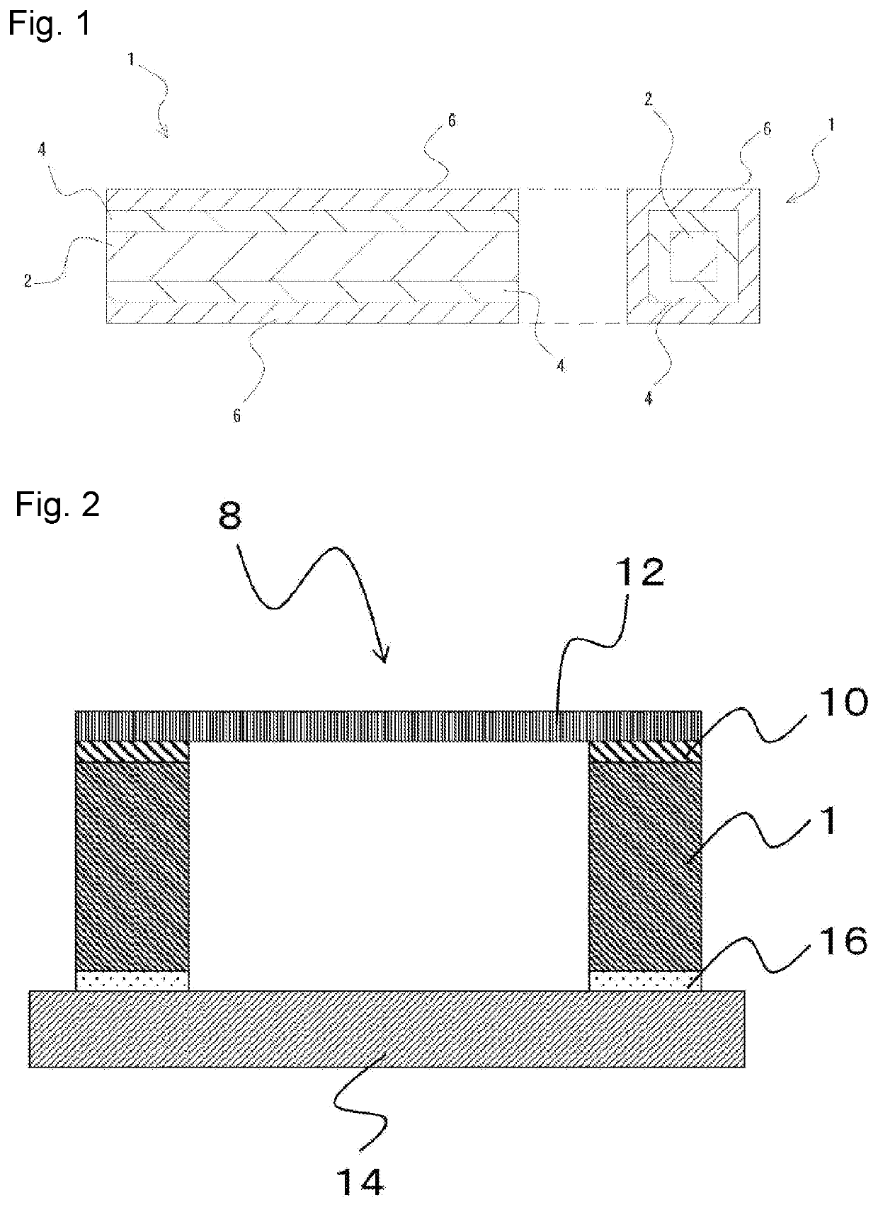
[0090]A main body of a support frame for pellicle with a frame shape having outer dimensions of 155 mm×125 mm×thickness 5 mm made of JIS A 7075 aluminum alloy (JIS A 7075-T 6) which was treated according to the temper designation T6 shown in JIS H 0001 was subjected to the anodizing treatment, and thereafter, an inorganic coating agent (Permeate 100) available from Day & Day Co., Ltd. was applied to be a thickness of about 15 μm and subjected to baking treatment to obtain a present support frame 1 for pellicle. The anodizing treatment was carried out in an anodizing bath of an alkaline aqueous solution (pH=14) where 1 wt % of sodium hydroxide (NaOH) was dissolved, at an electrolytic voltage of 20 V and at a bath temperature of 10° C. for 30 minutes. The baking treatment was carried out under the condition of 100° C. for 1 hour.

Example

Example 2
[0091]A present support frame 2 for pellicle was obtained in the same manner as in Example 1 except that the coating thickness of the inorganic coating agent (Permeate 100) was about 30 μm.

Example

Example 3
[0092]A present support frame 3 for pellicle was obtained in the same manner as in Example 2, except that hot water washing was performed after the baking treatment.

PUM

PropertyMeasurementUnit
Temperature80.0°C
Fraction2.0E-7fraction
Fraction1.0E-7fraction

Description & Claims & Application Information

We can also present the details of the Description, Claims and Application information to help users get a comprehensive understanding of the technical details of the patent, such as background art, summary of invention, brief description of drawings, description of embodiments, and other original content. On the other hand, users can also determine the specific scope of protection of the technology through the list of claims; as well as understand the changes in the life cycle of the technology with the presentation of the patent timeline. Login to view more.

Similar technology patents

Lamiinate-type power storage element and manufacturing method thereof

ActiveUS20170214032A1efficiently manufacture
Owner:FDK CORP

Method for manufacturing module component

ActiveUS20190096701A1efficiently manufacturehigh integration and miniaturization
Owner:MURATA MFG CO LTD

Optical path switching device

InactiveUS20050270632A1efficiently manufacture
Owner:SHARP KK

Method for Manufacturing a Three-Dimensionally Deformable, Sheet-Like Refinforcing Structure

ActiveUS20100291335A1efficiently manufacture
Owner:ESC EXTENDED STRUCTURED COMPOSITES

Container and method and device for manufacturing of such containers

InactiveUS20090134346A1efficiently manufactureadvantage in use
Owner:EIDE HALLVAR +1

Classification and recommendation of technical efficacy words

  • efficiently manufacture

Method and apparatus for manufacturing a device

InactiveUS7052268B2efficiently manufacture
Owner:BECTON DICKINSON & CO

Extrusion Die and Process for Producing an Extruded Filled Polymer Composition

InactiveUS20090146339A1efficiently manufacture
Owner:MALONE BRUCE A +1

Multilayer ceramic capacitor and method for manufacturing the same

ActiveUS20160268046A1efficiently manufacture
Owner:MURATA MFG CO LTD
Why Eureka
Try Eureka