Assembly for placement of a cardiac, aortic or arterial implant with stimulation assistance by a peripheral venous or arterial catheter

a technology of aortic or aortic valve and a catheter, which is applied in the direction of prosthesis, therapy, application, etc., to achieve the effects of reducing complications, facilitating connection, and being simpler and faster to carry ou

Active Publication Date: 2021-02-04
ELECTRODUCER
View PDF3 Cites 1 Cited by
  • Summary
  • Abstract
  • Description
  • Claims
  • Application Information

AI Technical Summary

Benefits of technology

[0074]By virtue of the peripheral venous catheter according to the invention, which integrates an electrically conductive element at the periphery of its sheath, it is no longer necessary to place a needle in the subcutaneous tissues or a cutaneous electrode to serve as a support for the electrode, typically the anode of a cardiac stimulator.
[0114]increased safety of a TAVI intervention or any other type of cardiac intervention (mitral valve, tricuspid valve) or any type of peripheral vascular intervention, since the (accessory) peripheral catheter is withdrawn last during the procedure. With the accessory catheter and therefore the connection to the cardiac stimulator installed at the very last moment, cardiac stimulation can be initiated even in an emergency situation;

Problems solved by technology

These successive steps of the operation have the major disadvantages of entailing a relatively long period of hospitalization of the patient, of being complex and costly, and of being limited to only some of the patients affected, since the physician and / or surgeon often considers that so-called “open heart” surgery cannot be performed because it is too risky in light of the general state of the patient, especially on account of the heart having to be stopped and of extracorporeal circulation having to be provided.
However, it has been felt that the existing techniques are not entirely satisfactory and that they may be improved.
In particular, these techniques have the following major disadvantages:they always require the patient to be placed under extracorporeal circulation; they are difficult to implement in practice;they do not permit precise control of the diameter by which the native valve is cut, with a view to subsequent calibration of the prosthetic valve;they entail risks of diffusion of fragments of the often calcified native valve within the body, which may lead to an embolism;they entail risks of perforating the wall of the aorta or heart;they entail risks of acute regurgitation of blood during the ablation of the native valve.
Firstly, such a probe constitutes a central venous access with an added risk of vascular complication in the targeted population of patients.
Secondly, this probe is relatively rigid.
Hence, its placement in the right ventricle, which is fragile and whose wall is finer than that of the left ventricle, poses a considerable risk of the phenomenon well known to interventionalists under the term “tamponade” which is a manifestation of substantial circulatory insufficiency, which may even lead to the death of the patient.
It should also be noted that this risk exists both during the intervention, that is to say during the placement of the electrosystolic probe, and also in the post-operative period, on account of the mobilization of the patients in their beds and therefore of the probe which is still present and which may then pierce the wall of the right ventricle.
Moreover, there is a risk of the electrosystolic stimulation probe moving at the crucial moment of placement of the valve.
This is because a stimulation probe is not fixed in a wall of the heart and may therefore move and thus generate a loss of capture of the electrical stimulation signal.
The heart is then no longer stimulated and therefore performs substantial movements, which impede the placement of the valve or of the balloon.
Another risk associated with the use of such probes is the risk of infection at the puncture site.
Finally, an interventionalist does not consider as negligible the additional operating time associated with the placement of a temporary stimulation probe, which is an operation that is not always easy to perform.
The disadvantage of the above application is that it requires the production of specific introducers or delivery catheters.

Method used


Image

  • Assembly for placement of a cardiac, aortic or arterial implant with stimulation assistance by a peripheral venous or arterial catheter
  • Assembly for placement of a cardiac, aortic or arterial implant with stimulation assistance by a peripheral venous or arterial catheter
  • Assembly for placement of a cardiac, aortic or arterial implant with stimulation assistance by a peripheral venous or arterial catheter

Examples


Embodiment Construction

[0117]Other advantages and features of the invention will become clearer on reading the detailed description of the invention, which is given by way of a non-limiting example and with reference to the accompanying figures, in which:

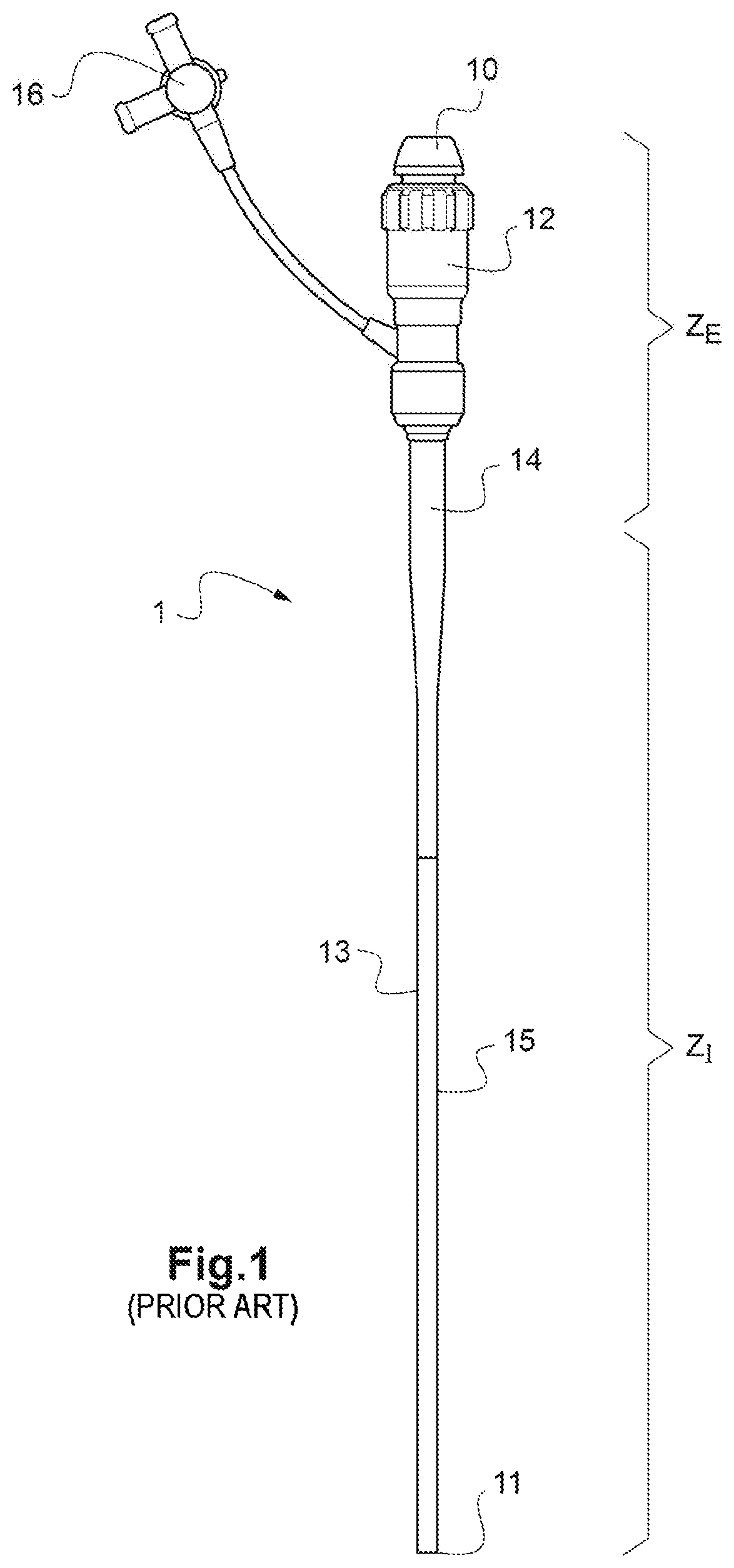
[0118]FIG. 1 is a perspective view of an introducer according to the prior art, intended to be introduced into a femoral artery in the groin region of a patient;

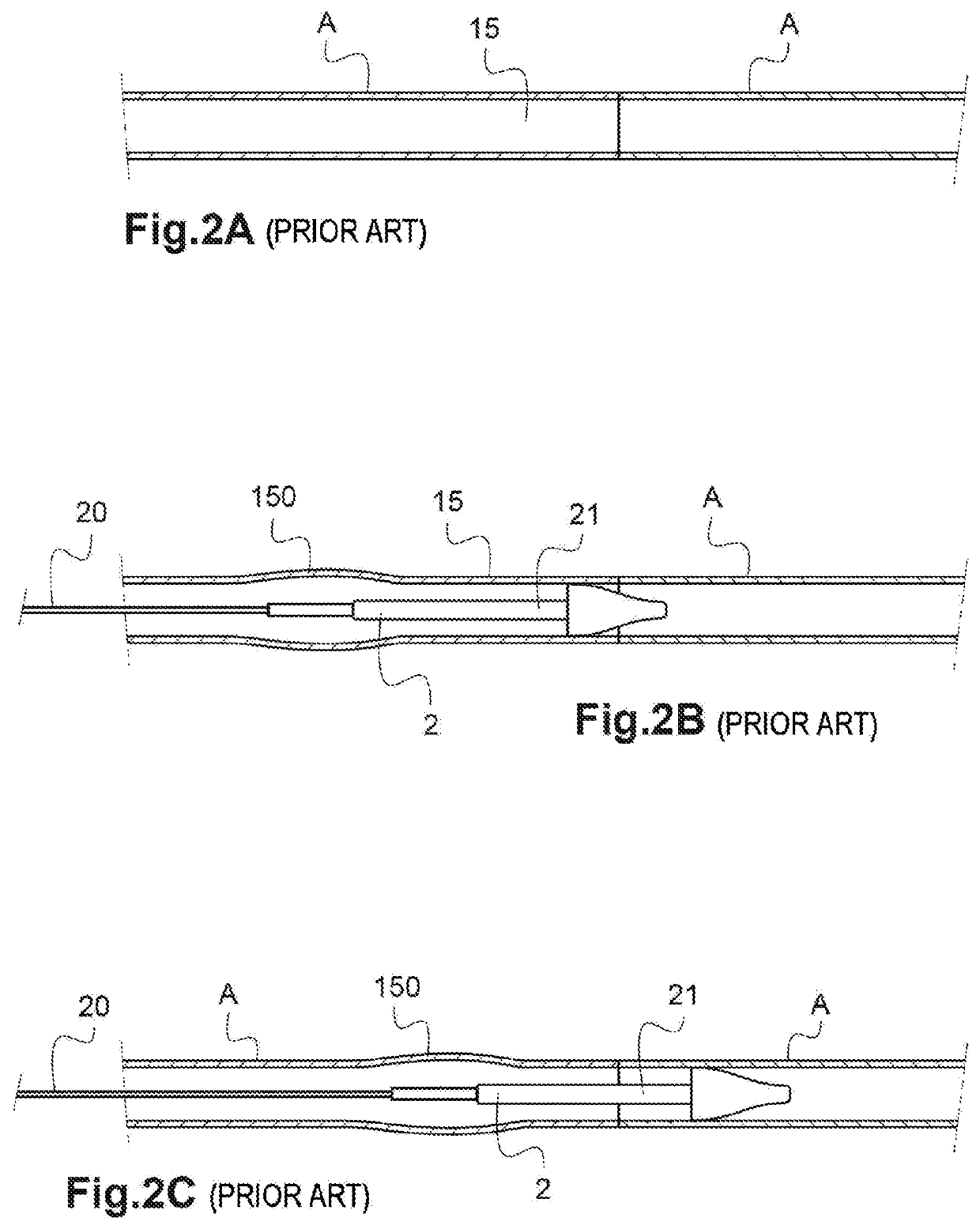
[0119]FIGS. 2A to 2C show, in partial longitudinal sectional views, various steps involved in sliding a valve catheter into the introducer according to FIG. 1, in order to fit an artificial valve in place as a replacement for a defective native aortic valve;

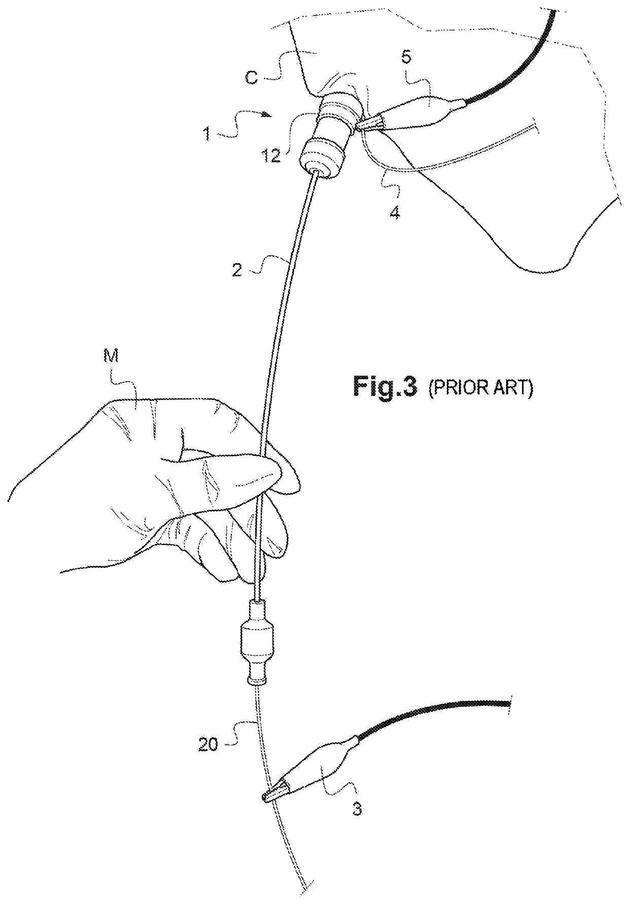
[0120]FIG. 3 shows, in a schematic perspective view from outside a patient, the step involving the placement of a valve catheter and of the cardiac stimulation electrodes according to the prior art;

[0121]FIG. 4 is a schematic perspective view of a delivery catheter according to the prior art, intended to be introduced directly into the artery o...


PUM


Abstract

An assembly for placement of a cardiac, aortic or arterial implant. The assembly includes an insertion sheath of an introducer or of a delivery catheter, which is of a size smaller than that of an introducer, intended to be introduced into an artery of a human body. The metal support of an electrode of the external cardiac stimulator being integrated into the insertion sheath of a peripheral venous or arterial accessory catheter, or a sleeve around the accessory catheter, which is introduced into the peripheral vein or artery of a patient. The sheath of the accessory catheter or the sleeve is therefore directly in contact with a peripheral vein or artery of the patient.

Description

TECHNICAL FIELD[0001]The present invention relates to an assembly for placement of a cardiac, aortic or arterial implant.[0002]A “cardiac or aortic implant” is understood here, and in the context of the invention, as a prosthetic cardiac or aortic valve intended for the replacement of a native valve.[0003]A preferred use is the replacement of a cardiac valve by a percutaneous route, comprising a valve delivery catheter and optionally an insertion device, commonly called an “introducer”.[0004]An operation for replacement of a cardiac valve by a percutaneous route is usually known by the abbreviation TAVI (transcatheter aortic valve implantation).[0005]Although described with reference to the replacement of an aortic valve, the assembly according to the invention can equally be used for the replacement of another valve of the heart, for example the tricuspid valve or the mitral valve.[0006]An “arterial implant” is understood here, and in the context of the invention, as a prosthetic d...

Claims


Application Information

Patent Timeline
Patent Type & Authority Applications(United States)
IPC IPC(8): A61B17/34A61B17/00A61B17/22A61N1/362
CPCA61B17/3468A61B17/00234A61B17/22A61B2017/00292A61B2017/00243A61B2017/22097A61N1/362A61B2017/00044A61N1/056A61F2/2436A61N1/3625
Inventor FAURIE, BENJAMIN
Owner ELECTRODUCER
Why Eureka
Try Eureka