
Mn ferrite powder, resin composition, electromagnetic wave shielding material, electronic material, and electronic component

Pending Publication Date: 2021-02-18
POWDERTECH
View PDF0 Cites 0 Cited by
  • Summary
  • Abstract
  • Description
  • Claims
  • Application Information

AI Technical Summary

Benefits of technology

The present invention provides a Mn ferrite powder that has excellent shielding properties against electromagnetic waves in both low- and high-frequency regions. This invention also provides an electromagnetic wave-shielding material, an electronic material, and an electronic component that have excellent shielding properties against low- and high-frequency electromagnetic waves. Additionally, this patent text provides a resin composition that can be used for producing the electromagnetic wave-shielding material, electronic material, and electronic component.

Problems solved by technology

However, conventional electromagnetic wave-shielding materials only have an electromagnetic wave-shielding property insufficient in a high-frequency band (e.g., a frequency band of more than 1 GHz and 12 GHz or less).
In addition, ferrite particles having a specific size and crystal structure are also known (e.g., Patent Literature 4), but even when such ferrite particles are used, satisfactory results cannot be obtained.

Method used


Image

  • Mn ferrite powder, resin composition, electromagnetic wave shielding material, electronic material, and electronic component

Examples


example 1

[0169]First, Fe2O3 and Mn3O4 as raw materials were blended at a predetermined ratio and were mixed by a Henschel mixer for 15 minutes.

[0170]The pulverized product thus obtained was pelletized by using a roller compactor, and then calcined in the air at 900° C. for 5 hours by using a rotary kiln.

[0171]After the calcination, water was added thereto and pulverization (wet pulverization) was performed to obtain a slurry. The volume average particle diameter of the powdery calcined body (calcined powder) (also referred to as raw material powder) contained in the slurry was 1.5 μm.

[0172]Next, the obtained slurry was granulated with a spray dryer and classified to obtain a granulated product having a volume average particle diameter of 5 μm.

[0173]Thereafter, thermal spraying was performed on the obtained granulated product, in a combustion flame of a combustible gas of propane gas: oxygen gas=10 Nm3 / hr: 35 Nm3 / hr at a flow rate of 40 m / sec. At this time, since the granulated product was th...

examples 2 and 3

[0180]Ferrite powders were produced in the same manner as in Example 1 except that the classification conditions were changed.

example 4

[0182]The ferrite powder of this example was produced by mixing the ferrite powder obtained in Example 3 and the ferrite powder obtained in Comparative Example 1 in a mass ratio of 80:20.

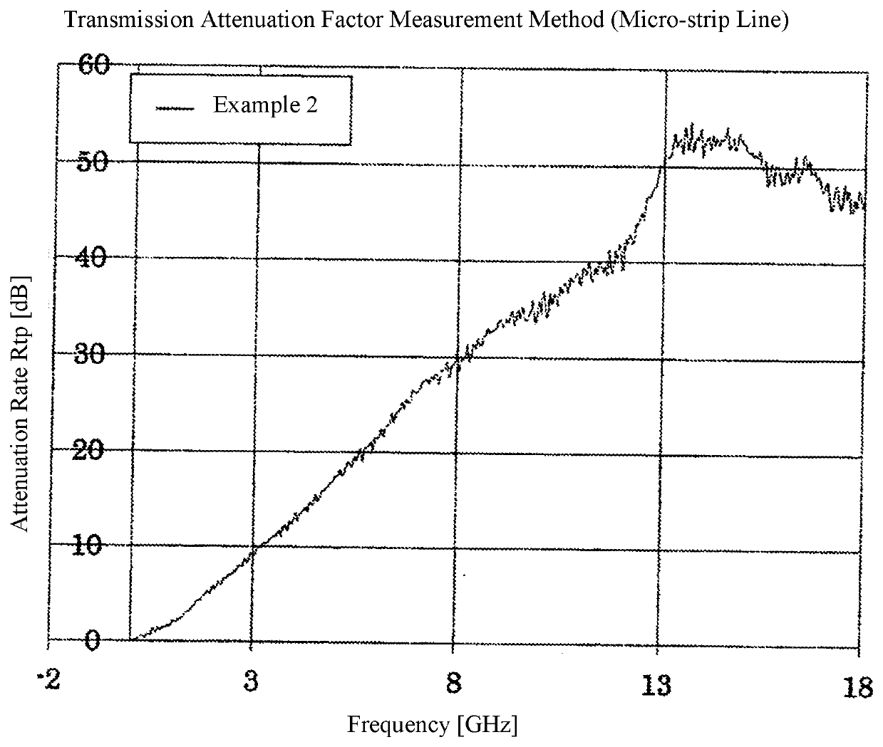
[0183]The production conditions of the ferrite powders of the respective Examples and Comparative Examples are summarized in Table 1, and the configurations of the ferrite powders of the respective Examples and Comparative Examples are summarized in Table 2.

[0184]The content of each metal element constituting the ferrite powder was determined by measurement using an ICP analyzer.

[0185]More specifically, 0.2 g of the ferrite powder was weighed, and 60 mL of pure water to which 20 mL of 1N hydrochloric acid and 20 mL of 1N nitric acid were added was heated, to prepare an aqueous solution in which the ferrite powder was completely dissolved. Thereafter, the aqueous solution was measured by using an ICP analyzer (ICPS-1000IV manufactured by Shimadzu Corporation) to determine the content of each metal el...


PUM

PropertyMeasurementUnit
Lengthaaaaaaaaaa
Lengthaaaaaaaaaa
Percent by massaaaaaaaaaa

Abstract

Provided are: an Mn ferrite powder characterized by including a plurality of ferrite particles, having a volume-average particle diameter of 1-10 μm, and having a 2.106 μm volume-based cumulative distribution (sieved) of 0.1-50.0 vol %; and a resin composition characterized by including said powder and a resin material.

Description

TECHNICAL FIELD[0001]The present invention relates to a Mn ferrite powder, a resin composition, an electromagnetic wave-shielding material, an electronic material, and an electronic component.BACKGROUND ART[0002]It is known to use a ferrite powder in an electromagnetic wave-shielding material (see, e.g., Patent Literatures 1, 2, and 3).[0003]As the electromagnetic wave-shielding material using a ferrite powder, an electromagnetic wave-shielding material obtained by molding a resin composition containing a ferrite powder into a sheet shape may be considered. When the sheet-shaped electromagnetic wave-shielding material is attached to a digital electronic device such as a personal computer and a mobile phone, which requires to shield electromagnetic waves, the leakage of electromagnetic waves to the outside of the electronic device can be prevented, the mutual interference of electromagnetic waves between circuits inside the electronic device can be prevented, or malfunction of the el...

Claims


Application Information

Patent Timeline
IPC IPC(8): C01G49/00C08L29/04H05K9/00
CPCC01G49/0072C08L29/04C08K3/22C01P2006/12H05K9/0081H01F1/37H01F1/344H05K9/0083C01P2004/61C01P2004/32C01P2006/11C01P2006/10C01P2006/42C01P2006/40C01P2006/22C01P2004/51C08K3/24C08K2003/2265C08K2201/01C08K2201/006C08K2201/005H01F1/36C01G49/0018
Inventor AGA, KOJIKOJIMA, TAKASHIISHII, KAZUTAKAIGARASHI, TETSUYAKUWAHARA, SHO
Owner POWDERTECH
Learn More