

Continuous microparticle manufacture
a technology of microparticles and manufacturing methods, applied in the direction of antineoplastic agents, organic active ingredients, drug compositions, etc., can solve the problems of particle instability, low drug loading of microparticles, time-consuming and impractical large-scale operations, etc., to reduce the residence time of formed microparticles and high drug loading levels
- Summary
- Abstract
- Description
- Claims
- Application Information
AI Technical Summary
Benefits of technology
Problems solved by technology
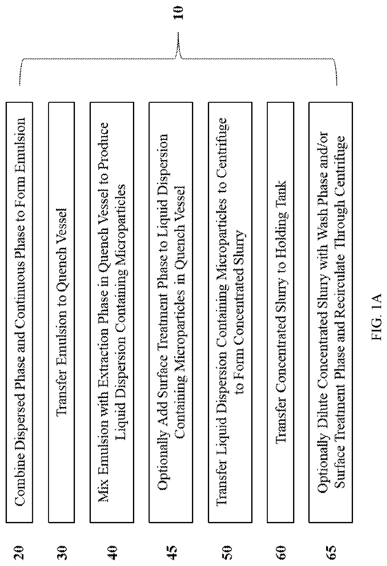
Method used
Image

Examples
example 1
of Risperidone-Containing Microparticles Using Plug Flow Reactor and TWHFTFF
[0307]Dispersed phase is prepared by mixing a 180 mg / mL solution of polylactic-co-glycolic acid (PLGA) / monomethoxy polyethylene glycol-PLGA (mPEG) (99:1 mixture) in dichloromethane (DCM) with a 50.1 mg / mL solution of risperidone in dimethylsulfoxide (DMSO) in the dispersed phase tank until a homogenous solution is achieved. Continuous phase is prepared from 0.25% PVA and water in the continuous phase tank. The dispersed phase and the continuous phase are fed through their respective conduits into the in-line mixer. The dispersed phase is passed through a hydrophobic PTFE filter and fed into the in-line mixer at a rate of 20 mL / min via conduit. The continuous phase is passed through a hydrophilic PVDF filter (0.20 μm) and fed into the in-line mixer at a rate of 2000 mL / min via conduit. An impeller in the in-line mixer rotating at 4000 rpm provides sufficient mixing of the dispersed phase and continuous phase ...
example 2
of Risperidone-Containing Microparticles Using Continuous Centrifugation
[0308]Dispersed phase is prepared by mixing a 180 mg / mL solution of polylactic-co-glycolic acid (PLGA) / monomethoxy polyethylene glycol-PLGA (mPEG) (99:1 mixture) in dichloromethane (DCM) with a 50.1 mg / mL solution of risperidone in dimethylsulfoxide (DMSO) in the dispersed phase tank until a homogenous solution is achieved. Continuous phase is prepared from 0.25% PVA and water in the continuous phase tank. The dispersed phase and the continuous phase are fed through their respective conduits into the in-line mixer. The dispersed phase is passed through a hydrophobic PTFE filter and fed into the in-line mixer at a rate of 20 mL / min via conduit. The continuous phase is passed through a hydrophilic PVDF filter (0.20 μm) and fed into the in-line mixer at a rate of 2000 mL / min via conduit. An impeller in the in-line mixer rotating at 4000 rpm provides sufficient mixing of the dispersed phase and continuous phase to p...
example 3
s Centrifugation as a Separation Process to Remove Small Particles
[0309]Continuous centrifugation was incorporated in the production of surface treated particles (STP) as a separation process in order to remove to small particles as well as to wash and concentrate the particles. This process separates out small particles continuously from the larger particles by centrifugation and discharges the retained larger particles at the end of the cycle. The continuous centrifugation was performed with the UniFuge Pilot separation system from Pneumatic Scale Angelus. FIG. 1M and FIG. 1N refer to Centrifuge 1, Centrifuge 2, Centrifuge 3, and Centrifuge 4.
[0310]Centrifuge 1 occurs concurrently with a homogenization step for approximately 2 hours for a 200 g scale batch: as the dispersed phase (DP) and continuous phase (CP) were mixed in homogenizer, the resulting liquid coming out of the homogenizer flowed into a glass vessel. The vessel's volume is much less than the total liquid volume that ...
PUM
| Property | Measurement | Unit |
|---|---|---|
| Temperature | aaaaa | aaaaa |
| Length | aaaaa | aaaaa |
| Pore size | aaaaa | aaaaa |
Abstract
Description
Claims
Application Information