Continuous drying apparatus for bee pollen and related drying method

a technology of continuous drying and bee pollen, which is applied in the field of continuous drying apparatus for bee pollen, can solve the problems of reducing the amount of bee pollen harvested by beekeepers, affecting the drying effect of bee pollen, so as to accelerate the drying temperature of bee pollen to be dried and improve the energy utilization rate. , the effect of increasing the drying rate of bee pollen to be don

Active Publication Date: 2021-09-23
BEE RES INST CHINESE ACAD OF AGRI SCI
View PDF0 Cites 9 Cited by
  • Summary
  • Abstract
  • Description
  • Claims
  • Application Information

AI Technical Summary

Benefits of technology

[0023]The continuous drying apparatus for bee pollen provided by the invention has at least one of the following advantages as compared with the prior art:
[0024]The heat pump dehumidification heating structure is started when drying the bee pollen to be dried, and the heat pump dehumidification heating structure can dehumidify and heat the bee pollen to be dried. Specifically, the heat pump dehumidification heating structure can effectively reduce the humidity in the inner chamber of the box body, and at the same time, it can recycle the latent heat and sensible heat in the dried exhaust gas, thereby greatly improving the energy utilization rate. However, since the heat pump dehumidification heating structure belongs to medium-low temperature drying, the temperature rises slowly in the early stage of drying, and thus, in order to accelerate the drying temperature of the bee pollen to be dried, the bee pollen fell from the bee pollen feed port is heated by the first drying conveying structure, and the heated bee pollen is conveyed in a direction close to the opening, and at the same time, the bee pollen fell from the opening is heated by the second drying conveying structure, and the heated dried bee pollen is conveyed in a direction close to the bee pollen discharge port. Thus, the present application achieves continuous drying of bee pollen by means of belt-type material conveying, thereby greatly increasing the drying rate of the bee pollen to be dried. In addition, it should be noted that during the drying process of the bee pollen to be dried, the whole drying process is in a closed-loop drying system, which is beneficial to retain the volatile components in the bee pollen and improve the product quality of the bee pollen. The heat transfer medium is usually an inert gas, thereby effectively reducing the degree of oxidative degradation of the biologically active substances of the bee pollen. In the later storage process of bee pollen, the storage medium of the finished product bin is an inert gas, which will greatly reduce the adverse effects caused by oxygen, microorganisms and humidity on the quality of the products.
[0025]Finally, the thickness of the material to be dried is adjusted by the cooperation of the baffle plate of the raw material bin and the conveyor belt to achieve thin layer drying, and the belt-type drying also effectively increases the drying area, increases the drying rate and shorten the drying time. The materials will automatically flip during the belt-type conveying process, which effectively overcomes the uneven drying of the materials, and is beneficial to improving the quality of the dried product. The present invention relates to a novel drying apparatus which combines conduction, radiation, convection and thin layer drying, and is suitable not only for drying bee pollen but also for drying processing of other heat sensitive materials.

Problems solved by technology

However, due to restrictions on the conditions such as post-harvest preservation, drying, storage and transportation often causes beekeepers to reduce the amount of bee pollen harvested.
After fresh bee pollen is harvested, the moisture content is as high as 20% to 30% in wet basis, the activities of microorganisms and enzymes are very high, and it needs to be dried in time, otherwise, the bee pollen will rapidly ferment and deteriorate, the active ingredients will be lost, and the market value will be lost.
However, these methods are generally difficult to effectively protect the nutritional ingredients and active substances in the bee pollen as they are easy to cause fat oxidation, color change and the like during the drying process, thereby causing poor quality of the dried bee pollen.
In addition, low energy utilization and high energy consumption are commonly existed for these drying methods, which leads to high cost of the drying processing of the bee pollen.

Method used


Image

  • Continuous drying apparatus for bee pollen and related drying method
  • Continuous drying apparatus for bee pollen and related drying method
  • Continuous drying apparatus for bee pollen and related drying method

Examples


example 1

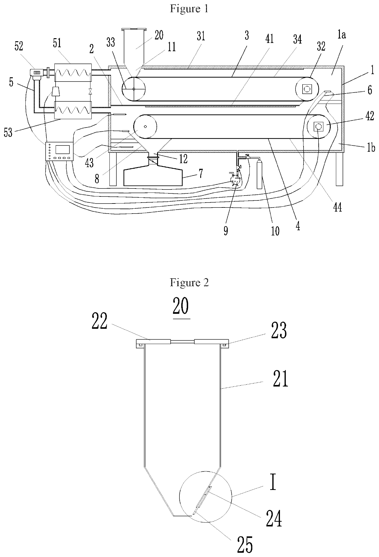
[0034]As shown in FIG. 1, the figure schematically shows that the continuous drying apparatus for bee pollen comprises: a box body 1, a partition plate 2, a first drying conveying structure 3, a second drying conveying structure 4, and a heat pump dehumidification heating structure 5.

[0035]In the Example of the present application, a bee pollen feed port 11 and a bee pollen discharge port 12 are respectively constructed on the box body 1, a partition plate 2 is disposed inside the box body 1, and the partition plate 2 separates the inner chamber of the box body 1 into an upper chamber 1a and a lower chamber 1b, wherein the free end of the partition plate 2 forms an opening together with the side wall of the box body 1. It should be noted that, the “opening” is commonly constructed by the free end of the partition plate 2, the front side wall, the rear side wall and the right side wall of the box body 1.

[0036]In addition, it should be noted that the partition plate 2 needs to have a ...


PUM


Abstract

The present invention relates to the technical field of bee product processing, and discloses a continuous drying apparatus for bee pollen and related drying method. The continuous drying apparatus for bee pollen comprises: a box body; a first drying conveying structure; a second drying conveying structure; and a heat pump dehumidification heating structure. The continuous drying apparatus for bee pollen has the advantage of high drying efficiency.

Description

CROSS-REFERENCE[0001]The present application claims the priority to Chinese Patent Application No. 2018101465485, entitled “Continuous drying apparatus for bee pollen and related drying method”, filed on Feb. 12, 2018 with the CNIPA, which is incorporated herein by reference in its entirety.TECHNICAL FIELD[0002]The present invention relates to the technical field of bee product processing, in particular to a continuous drying apparatus for bee pollen and related drying method.BACKGROUND ART[0003]Bee pollen is derived from nature, and is an irregular oblate lump formed by adding special gland secretions to pollen grains or nectar collected by bees and mixing the resultant. As the source of plant life, bee pollen contains all the nutritional ingredients and active substances for plant development, and it is often called “micro-nutrition library”. The total production of bee pollen in China is the highest in the world. However, due to restrictions on the conditions such as post-harvest...

Claims


Application Information

Patent Timeline
Patent Type & Authority Applications(United States)
IPC IPC(8): F26B5/04F25B30/00F26B17/04F26B23/00F26B23/10F24F3/14
CPCF26B5/041F25B30/00F26B17/04F24F2003/144F26B23/10F24F3/14F26B23/00F26B5/04F26B25/00A23L21/20F26B17/08F26B21/086F26B3/283
Inventor PENG, WENJUNFANG, XIAOMINGWU, LIMINGTIAN, WENLIGAO, LINGYUZHAO, YAZHOUTONG, YUEMINXIAO, HONGWEIHAN, SHENGMING
Owner BEE RES INST CHINESE ACAD OF AGRI SCI
Why Eureka
Try Eureka