

IGBT And Manufacturing Method Therefor
a technology which is applied in the field of igbt and manufacturing method therefor, can solve the problem of limiting the further improvement of the current igbt performan
- Summary
- Abstract
- Description
- Claims
- Application Information
AI Technical Summary
Benefits of technology
Problems solved by technology
Method used
Image

Examples
embodiment 1
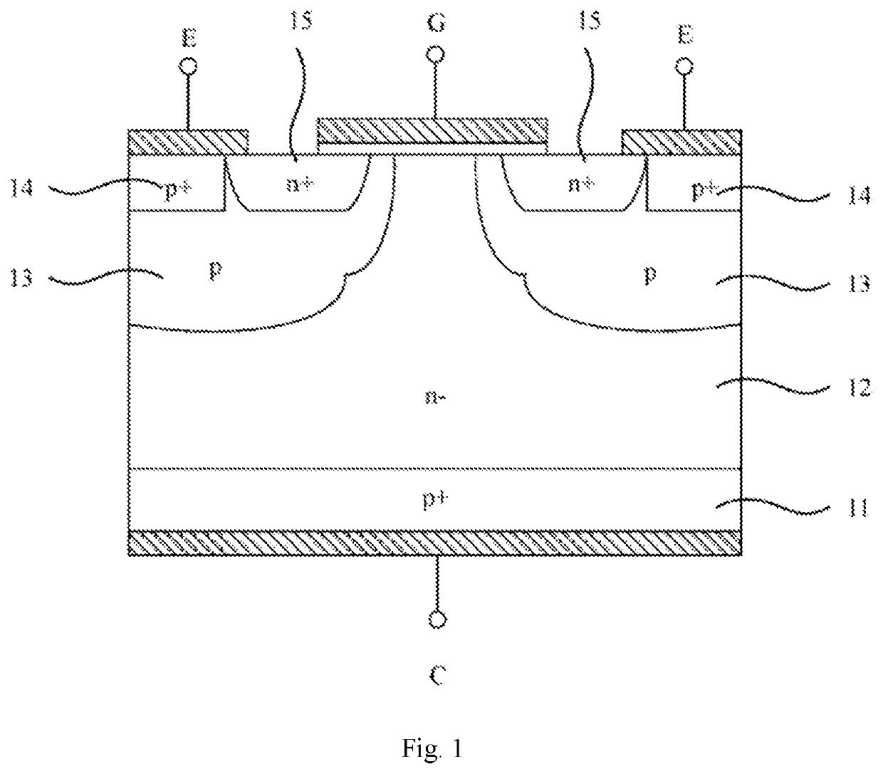
[0028]This embodiment provides an IGBT, and FIG. 1 shows a schematic structural diagram of this embodiment. Referring to FIG. 1, the IGBT of this embodiment comprises from bottom to top:
[0029]A collector C on the back surface of the IGBT, a P-type substrate 11, an N-type drift region 12, a P-type well region 13 at both ends of the N-type drift region 12, a P-type source region 14 and an N-type source region 15 above the P-type well region 13, an emitter electrode E located above the P-type source region 14 and a part of the N-type source region 15, and a gate electrode G located above a part of the N-type source region 15, a part of the P-type well region 13 and a part of the N-type drift region 12.
[0030]In the IGBT of this embodiment, a target region comprises at least one of the P-type substrate 11, the P-type well region 13, and the P-type source region 14. In this embodiment, the doping impurities of the target region are first ions, which have a diffusion coefficient greater th...
embodiment 2
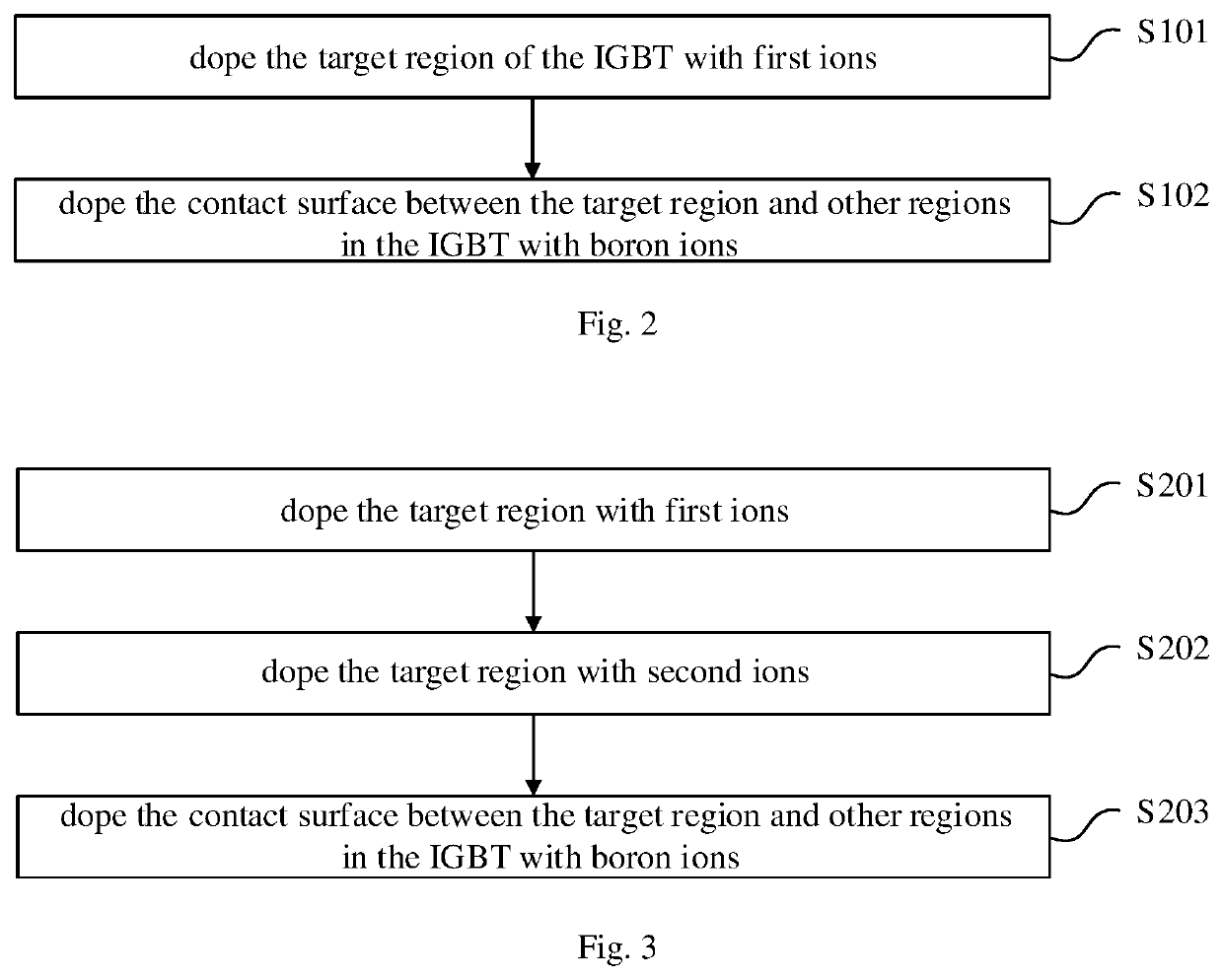
[0034]This embodiment provides a method for manufacturing IGBT, which is used for manufacturing the IGBT of embodiment 1, FIG. 2 shows a flowchart of this embodiment. Referring to FIG. 2, the method of this embodiment comprises:
[0035]S101, doping the target region of the IGBT with first ions;
[0036]S102, doping the contact surface between the target region and other regions in the IGBT with boron ions.
[0037]Therefore, according to the selection of the target region in embodiment 1, the corresponding P-type substrate 11, P-type well region 13, and P-type source region 14 can be specifically formed, wherein the first ions can be doped into the target region through but not limited to any one of ion implantation, diffusion, evaporation, and sputtering. In addition, boron ions can also be doped to specific contact surface through but not limited to the above-mentioned methods, to avoid metal contamination caused by doped metal ions.
embodiment 3
[0038]This embodiment provides an IGBT on the basis of embodiment 1. Specifically, the improvement of the IGBT of this embodiment over embodiment 1 lies in that the target region of this embodiment, that is, at least one of the P-type substrate 11, the P-type well region 13, and the P-type source region 14, in addition to being doped with the first ions, it is also doped with second ions, the diffusion coefficient of the second ions is not less than the diffusion coefficient of the boron ions. Specifically, the second ions may be, but not limited to, boron ions, aluminum ions, gallium ions, indium ions, thallium ions.
[0039]In this embodiment, the first ions are preferably aluminum ions, and the second ions are preferably gallium ions, or the first ions are preferably gallium ions, and the second ions are preferably aluminum ions. In addition, the first ions and the second ions can be doped with each other, or distributed in different layers according to specific applications. The do...
PUM
| Property | Measurement | Unit |
|---|---|---|
| diffusion coefficient | aaaaa | aaaaa |
| input impedance | aaaaa | aaaaa |
| on-voltage drop | aaaaa | aaaaa |
Abstract
Description
Claims
Application Information