Method and system for obtaining design scheme of collaboratively optimized integrated energy system

a technology of integrated energy system and design scheme, applied in power network operation system integration, instruments, data processing applications, etc., can solve the problems of complex and diversified integration forms, complex and diversified system structures, and deepen the multi-energy flow complexity of the system, so as to reduce energy consumption, cost and emission of design results, and optimize the network structure.

Pending Publication Date: 2021-10-28
SHANDONG UNIV
View PDF0 Cites 1 Cited by
  • Summary
  • Abstract
  • Description
  • Claims
  • Application Information

AI Technical Summary

Benefits of technology

[0040]The present disclosure constructs the unified model of the plurality of types of devices in the integrated energy system by using a uniform modeling method, and provides the operating manners and the control parameters of the types of devices; designs a mutual transformation method for the chain structure and the network structure, and optimizes the network structure by using the order of the devices in the chain structure; and designs an integrated design method for collaboratively optimizing the “system structure”, the “device capacity”, and the “operating parameters” by using the device order, the device capacity, and the control parameters as variables. Defects in an experience-based structure design method and disharmony of independent optimization of structure capacity parameters in the design of the integrated energy system are resolved, which not only decreases energy consumption, costs, and emission of a design result, but also simplifies calculation, and decreases workloads and time of the system design.
[0041]The present disclosure mines the complementary structural relationships among the plurality of types of energy conversion devices, and the intrinsic constraint relationship between the capacity configuration and the key operating parameters, and constructs an integrated optimization design method of integrated multi-energy complementary structure, device, and operation. The present disclosure is an integrated design method, and is an integrated design method that integrates the multi-energy complementary structure, the device capacity configurations, and the key operating parameters, which fundamentally resolves a problem of independent optimization failure caused by multi-device and multi-condition, structure complexity and diversity, and strong coupling of multi-energy flow operation.

Problems solved by technology

The system includes various types of energy conversion units, and integration forms are complex and diversified.
Access of intermittent renewable energy not only deepens multi-energy flow complexity of the system, but also brings in a large quantity of random factors for operating states, so that a coupling relationship between a capacity configuration and an operating mode in the system is further deepened actually.
Not only does model selection of power devices have decisive impacts on overall performance, but also disparate features of different power techniques lead to not exactly the same collaborative operating manners among the devices, so that system structures are complex and diversified.
As a result, a conventional multi-objective optimization method for a single structure or capacity is difficult to be competent, and therefore, a new integrated design method is required.
Therefore, a problem to be resolved in integrated design of the integrated energy system is determining system energy flow structures, device capacity and complementary operating manners by using performance as an optimization objective, and by using a device, energy, and system parameters as input.
However, if multi-objective optimization of device capacity and multi-objective optimization of operating parameters are completed respectively with an idea of nest optimization, an amount of calculation and a calculation time are doubled, and therefore it is difficult to find a solution accurately.
In addition, if the nest optimization of the structure of the integrated energy system is added, no solution can be found.

Method used


Image

  • Method and system for obtaining design scheme of collaboratively optimized integrated energy system
  • Method and system for obtaining design scheme of collaboratively optimized integrated energy system
  • Method and system for obtaining design scheme of collaboratively optimized integrated energy system

Examples


embodiment 1

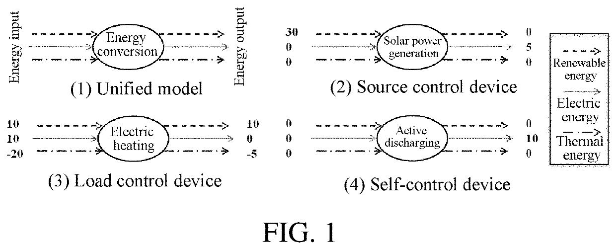
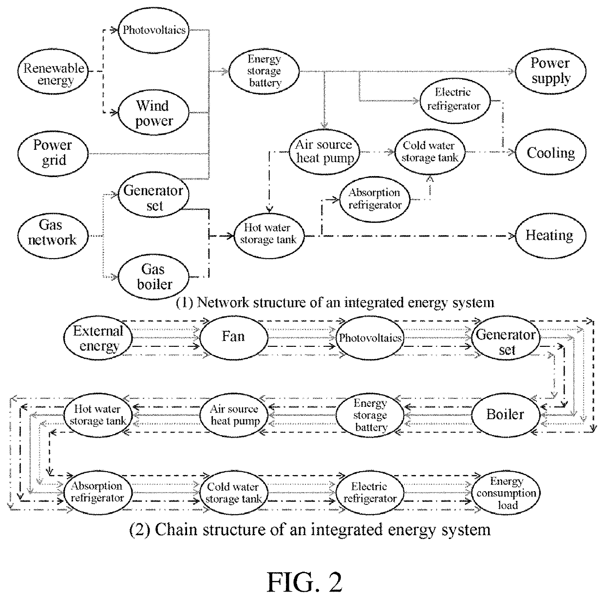
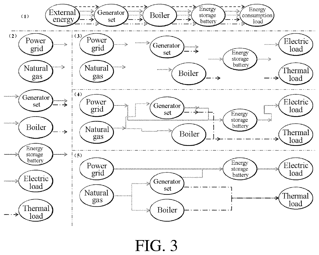
[0053]This embodiment discloses a method for obtaining a design scheme of a collaboratively optimized integrated energy system, which is an integrated design method. Based on a chain structure constructed by a unified model, this embodiment designs an integrated design method for collaboratively optimizing a “system structure”, “device capacity”, and “operating parameters” of the integrated energy system. In the integrated design method, by using a structure order, installed capacity, and control parameters of devices as variables, simulation is performed by using a chain operating mode to obtain operating data, and by using primary energy consumption, energy supply costs, and carbon emission as objectives, and by using an optimization method of a heuristic algorithm and an evaluation method of Pareto optimality, the variables are solved to obtain an optimization design result. The design method is specifically divided into the following four steps:

[0054](1) determining types of can...

embodiment 2

[0089]An objective of this embodiment is to provide a system for obtaining a design scheme of a collaboratively optimized integrated energy system, including:

[0090]a unified model construction module, determining types and a quantity of candidate devices, and taking a total quantity of devices as an upper limit of a length of the system during integrated optimization; and

[0091]determining, according to the total quantity of devices of the system and the types of the devices, a quantity and types of variables by using a unified model, the variables including a device order, device capacity, and operating parameters;

[0092]a chain structure construction module, representing the structure of the integrated energy system as a chain structure, based on the unified model of the devices; and

[0093]a solving module, performing simulation by using a chain operating mode of the chain structure to obtain operating data, and solving variables to obtain a ranking result of the devices in the chain...

embodiment 3

[0095]An objective of this embodiment is to provide a computing apparatus, including a memory, a processor, and a computer program stored in the memory and executable on the processor, where when the processor executes the program, the following steps are implemented, including:

[0096]determining types and a quantity of candidate devices, and taking a total quantity of devices as an upper limit of a length of the system during integrated optimization;

[0097]determining, according to the total quantity of devices of the system and the types of the devices, a quantity and types of variables by using a unified model, the variables including a device order, device capacity, and operating parameters;

[0098]representing the structure of the integrated energy system as a chain structure, based on the unified model of the devices;

[0099]performing simulation by using a chain operating mode of the chain structure to obtain operating data, and solving variables to obtain a ranking result of the d...


PUM


Abstract

A method and system for obtaining a design scheme of a collaboratively optimized integrated energy system which resolves a problem of independent optimization failure caused by multi-device and multi-condition, structure complexity and diversity, and strong coupling of multi-energy flow operation. The method includes: determining types and a quantity of candidate devices, and taking a total quantity as a system scale during optimization; determining a quantity and types of variables using a unified model representing the integrated energy system as a chain structure; performing simulation by using a chain operating mode to obtain operating data, and solving variables to obtain a ranking result of the devices in the chain structure, by using a structure order, installed capacity, and control parameters of the devices as variables, and by using primary energy consumption, energy supply costs, and carbon emission as objectives; and obtaining a system design result according to the solving result.

Description

BACKGROUNDTechnical Field[0001]The present disclosure relates to the technical field of integrated energy system planning, and in particular, to a method and a system for obtaining a design scheme of a collaboratively optimized integrated energy system.Related Art[0002]The description in this section merely provides background information related to the present disclosure and does not necessarily constitute the prior art.[0003]An integrated energy system meets integrated energy requirements of users on cooling, heating, and electricity simultaneously by using energy in a complementary manner, for example, solar energy, biomass energy, and natural gas, which dramatically improves an ability of the integrated energy system for dealing with load changes. The system includes various types of energy conversion units, and integration forms are complex and diversified. Access of intermittent renewable energy not only deepens multi-energy flow complexity of the system, but also brings in a ...

Claims


Application Information

Patent Timeline
Patent Type & Authority Applications(United States)
IPC IPC(8): G06Q50/06H02J3/14H02J13/00
CPCG06Q50/06H02J3/144H02J13/00004H02J2203/20H02J2310/12H02J2310/60H02J2310/64H02J13/00032G06Q10/04Y04S20/222Y02B70/3225Y02E40/70Y02E60/00Y04S10/50Y04S40/20
Inventor ZHANG, CHENGHUISUN, BOLI, HAORAN
Owner SHANDONG UNIV
Why Eureka
Try Eureka