Oxygen reduction reaction catalyst

a technology of reaction catalyst and oxygen reduction reaction, which is applied in the direction of organic compound/hydride/coordination complex catalyst, physical/chemical process catalyst, cell component, etc., can solve the problems of high cost of platinum, severe mass-transport limitations, and the power density performance obtained with state-of-the-art metal-n—c cathode cannot reach the level of pt-based catalys

Pending Publication Date: 2022-01-27
JOHNSON MATTHEY HYDROGEN TECH LTD
View PDF4 Cites 0 Cited by
  • Summary
  • Abstract
  • Description
  • Claims
  • Application Information

AI Technical Summary

Benefits of technology

[0038]The present inventors have found that they can determine the dioxygen electro-reduction activity of an ORR catalyst based on the material used to form it. In particular, they have determined that when deriving a Metal-N—C catalysts (Metal=Fe or Co) from a metal organic framework material by pyrolysis, the activity of the product can be predicted from certain characteristics of the starting material. Indeed, the predictive character of this structure / property relationship has permitted the selection of MOF materials that result in Metal-N—C catalysts with a higher electrocatalytic activity for O2 reduction than has been reported previously.
[0052]The large specific internal pore volume present in the MOFs before pyrolysis has been found to result in a higher catalytic activity of the final Fe—N—C catalysts formed after the pyrolysis step. This higher activity per mass of catalyst is due to either a modified carbonization process of MOFs during pyrolysis or due to the preferential formation of FeNxCy sites during pyrolysis, rather than the parallel formation of Fe / Co based crystalline structures inactive for ORR in acid electrolyte. This is surprising because the process for forming the Metal-N—C catalyst involves a profound structural change relative to the starting MOF. The good dispersion of Fe or Co ions in the catalyst precursors comprising MOFs with large specific internal pore volume may minimize the agglomeration of Fe or Co during pyrolysis, and maximize the formation of MetalNxCy (Metal=Fe or Co or a combination of both) active sites.
[0053]Preferably the synthesis targets MOF structures having large specific internal pore volume, but with a small crystal size (typically, 200 nm and less). This results in catalytic particles of reduced dimension and with improved access of oxygen to the active sites after pyrolysis.
[0069]Optionally, the method further comprises an acid washing step after the step of pyrolysing the MOF material. Zinc and Mg containing MOFs do not require an acid wash, though this can still be helpful to ensure the metal is fully removed. The acid wash may involve the use of HCl, H2SO4, HNO3 or HF. The acid washing (or etching) step serves to improve the pore network of the formed carbonaceous material, in particular the micropore network (pore size of 5-20 Å).
[0076]Advantageously, because of the activity of the catalyst, the catalyst can be provided as a cathode layer in a membrane electrode assembly (MEA), the cathode layer having a mean thickness of less than 60 microns. This permits good efficacy while avoiding the disadvantages of the prior art as discussed above. In particular, the catalyst can be incorporated as a layer applied to a membrane to form a catalyst coated membrane (CCM) or as a layer on a gas diffusion layer (GDL) to form a gas diffusion electrode (GDE), and then into the MEA of a PEMFC.

Problems solved by technology

However, platinum is an expensive material and it is desirable to find alternative materials for splitting the oxygen (O2) molecules in the cathode electrode of the fuel cell.
However, this leads to severe mass-transport limitations (arising from oxygen diffusion, water removal, electron and proton conduction issues across the thick cathode layer).
Overall, the power density performance obtained with state-of-the-art Metal-N—C cathodes does not reach that obtained with Pt-based catalysts, especially when operating under practical conditions and using air as the cathode reactant.
They also identified issues with the use of Co-ZIFs; one of them being the agglomeration of cobalt that needs to be removed to increase the catalyst activity to weight ratio.
However, encapsulation of metallic cobalt by carbon shells prevents the complete removal of inactive cobalt, and the high amount of cobalt in Co-ZIFs results in highly graphitic materials with a low number of active sites, and hence a moderate activity.

Method used


Image

  • Oxygen reduction reaction catalyst
  • Oxygen reduction reaction catalyst
  • Oxygen reduction reaction catalyst

Examples


examples

[0085]The invention will now be described in relation to the following non-limiting examples.

[0086]Measurement Techniques

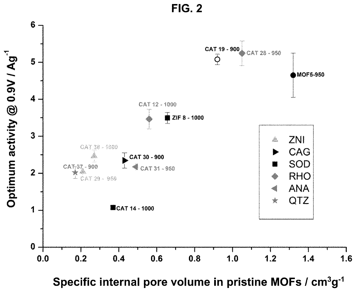
[0087]Specific Internal Pore Volume

[0088]The specific internal pore volume was calculated using crystallographic structures for each MOF. For that purpose, the crystal structure was first built following the single crystal data given in the literature for each solid. The geometry was optimised using Lennard Jones parameters and electrical charges to determine the positions of the atoms in the structure. In this case, the Universal Force Field (UFF) for Lennard Jones parameters was considered. Within the entire volume of optimized structures and following the strategy previously reported by Düren et al. (T. Duren, F. Millange, G. Férey, K. S. Walton, R. Q. Snurr, J. Phys. Chem. C, 2007, 111, 15350), a theoretical probe size of 0 Å was then used to determine the entire volume of the unit crystallographic cell. The unit cell is the smallest volume of a crystalline so...


PUM

PropertyMeasurementUnit
temperatureaaaaaaaaaa
sizeaaaaaaaaaa
diameteraaaaaaaaaa

Abstract

A method for the manufacture of an oxygen reduction reaction (ORR) catalyst, the method comprising;providing a metal organic framework (MOF) material having a specific internal pore volume of 0.7 cm3g−1 or greater;providing a source of iron and / or cobalt;pyrolysing the MOF material together with the source of iron and / or cobalt to form the catalyst,wherein the MOF material comprises nitrogen and / or the MOF material is pyrolysed together with a source of nitrogen and the source of iron and / or cobalt is disclosed.

Description

CROSS-REFERENCE TO RELATED APPLICATIONS[0001]The present application is a continuation of U.S. Ser. No. 15 / 757,171, filed Mar. 2, 2018, which is the National Stage of International Patent Application No. PCT / GB2016 / 052774, filed Sep. 8, 2016, which claims priority from Great Britain Patent Application No. 1515869.4 filed Sep. 8, 2015, the entire disclosures of each of which are incorporated herein by reference.FIELD OF THE INVENTION[0002]The present invention relates to a process for the manufacture of an oxygen reduction reaction (ORR) catalyst, and in particular to the manufacture of a cathode electrode comprising the catalyst for use in a fuel cell for the ORR. The invention provides an ORR catalyst with a high activity.BACKGROUND OF THE INVENTION[0003]A fuel cell is an electrochemical cell comprising two electrodes separated by an electrolyte. A fuel, such as hydrogen or an alcohol, such as methanol or ethanol, is supplied to the anode and an oxidant, such as oxygen or air, is s...

Claims


Application Information

Patent Timeline
Patent Type & Authority Applications(United States)
IPC IPC(8): H01M4/90H01M4/88B01J23/78B01J23/80B01J35/10B01J37/08B01J35/00B01J23/89H01M4/86
CPCH01M4/90H01M8/1011H01M4/9041B01J23/78B01J23/80B01J35/1047B01J35/1042B01J35/1038B01J37/086B01J35/002B01J23/8913B01J23/8906B01J35/0033H01M4/8668H01M4/8828H01M2008/1095B01J31/1691B01J2531/0205Y02E60/50B01J29/00H01M4/86H01M4/88H01M4/9008B01J2531/0213H01M2004/8689
Inventor ARMEL, MARIE JOSEPHE VANESSABENNETT, STEPHEN CHARLESJAQUEN, FREDERIC CHRISTOPHEJONES, DEBORAHHINDOCHA, SHEENASALLES, FABRICE
Owner JOHNSON MATTHEY HYDROGEN TECH LTD
Why Eureka
Try Eureka