
Lithium-silicon battery

a lithium-silicon battery and lithium-silicon technology, applied in the field of lithium-silicon batteries, can solve the problems of inferior silicon forms in the anode, large volume change of silicon, electrode deterioration and solid-electrolyte interphase (sei) instability, and achieve the effect of new properties

Pending Publication Date: 2022-02-24
GRP 14 TECH INC
View PDF0 Cites 14 Cited by
  • Summary
  • Abstract
  • Description
  • Claims
  • Application Information

AI Technical Summary

Benefits of technology

The patent provides a new material for the anode of a lithium-silicon battery that solves challenges in previous methods. The material is composed of a composite of silicon and carbon, with the silicon being amorphous, small, and embedded in a porous carbon scaffold. This composite is produced using a chemical vapor infiltration process during which silicon is embedded in the pores of the carbon scaffold. The resulting material has improved properties for use as an anode in lithium-silicon batteries.

Problems solved by technology

Silicon's large volume change (approximately 400% based on crystallographic densities) when lithium is inserted is one of the main obstacles along with high reactivity in the charged state to commercializing this type of anode.
Prior to this disclosure, performance of lithium-silicon batteries has been limited by inferior forms of silicon in the anode.
However, silicon exhibits large volume change during cycling, in turn leading to electrode deterioration and solid-electrolyte interphase (SEI) instability.
Thus far, techniques for creating nano-scale silicon involve high-temperature reduction of silicon oxide, extensive particle diminution, multi-step toxic etching, and / or other cost prohibitive processes.
Likewise, common matrix approaches involve expensive materials such as graphene or nano-graphite, and / or require complex processing and coating.
Despite these desirable electrochemical properties, amorphous carbons have not seen wide-spread deployment in commercial Li-ion batteries, owing primarily to low FCE and low bulk density (<1 g / cc).
Problems associated with this strategy include the lack of a suitable silicon starting material that is amenable to the coating process, and the inherent lack of engineered void space within the carbon-coated silicon core-shell composite particle to accommodate expansion of the silicon during lithiation.
This inevitably leads to cycle stability failure due to destruction of core-shell structure and SEI layer (Beattie S D, Larcher D, Morcrette M, Simon B, Tarascon, J-M.

Method used


Image

  • Lithium-silicon battery
  • Lithium-silicon battery
  • Lithium-silicon battery

Examples


example 1

n of Silicon-Carbon Composite Material by CVI

[0124]The properties of the carbon scaffold (Carbon Scaffold 1) employed for producing the silicon-carbon composite is presented in Table 3. Employing Carbon Scaffold 1, the silicon-carbon composite (Silicon-Carbon Composite 1) was produced by CVI as follows. A mass of 0.2 grams of amorphous porous carbon was placed into a 2 in.×2 in. ceramic crucible then positioned in the center of a horizontal tube furnace. The furnace was sealed and continuously purged with nitrogen gas at 500 cubic centimeters per minute (ccm). The furnace temperature was increased at 20° C. / min to 450° C. peak temperature where it was allowed to equilibrate for 30 minutes. At this point, the nitrogen gas is shutoff and then silane and hydrogen gas are introduced at flow rates of 50 ccm and 450 ccm, respectively for a total dwell time of 30 minutes. After the dwell period, silane and hydrogen were shutoff and nitrogen was again introduced to the furnace to purge the ...

example 3

Various Silicon-Composite Materials

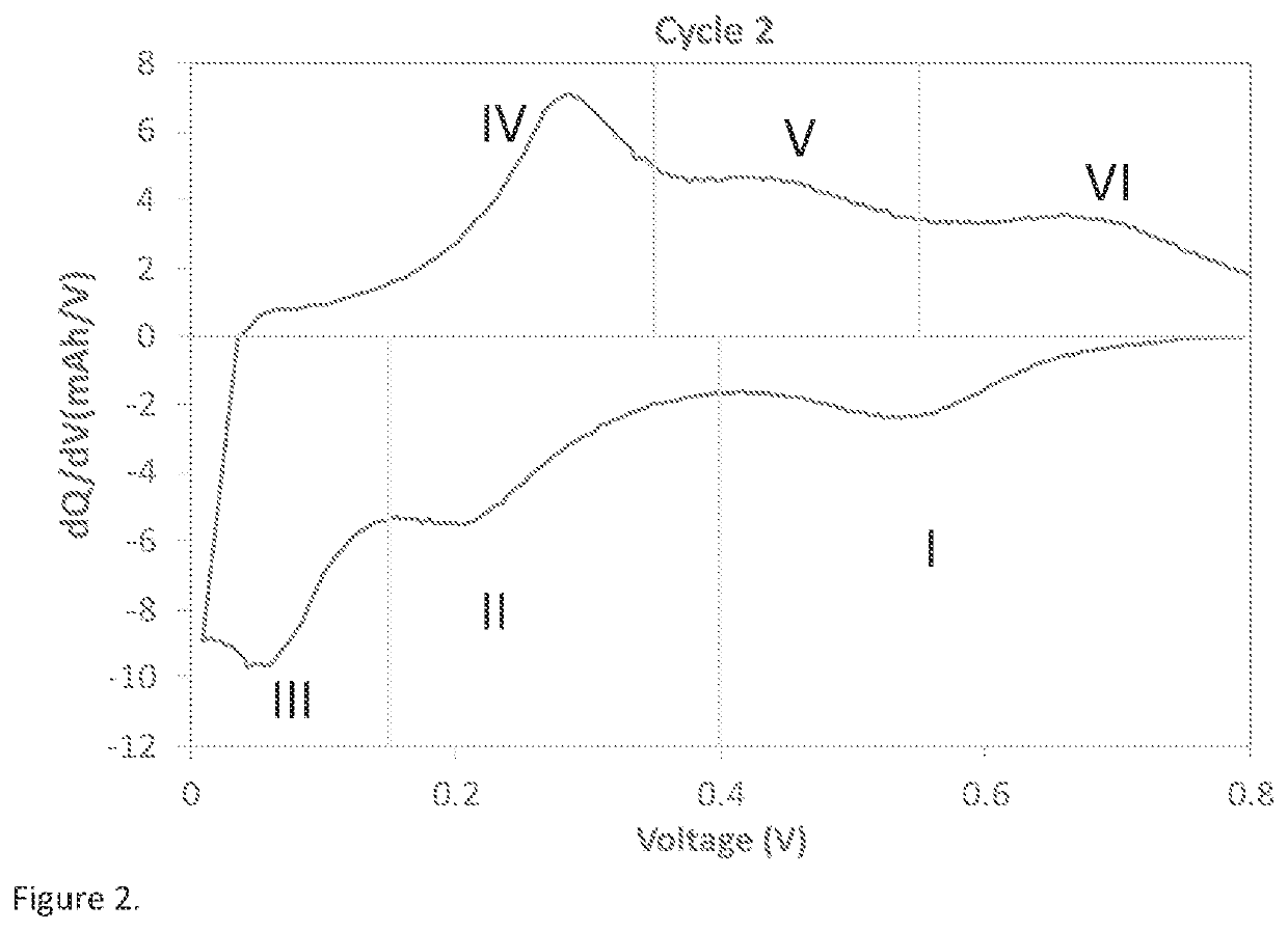
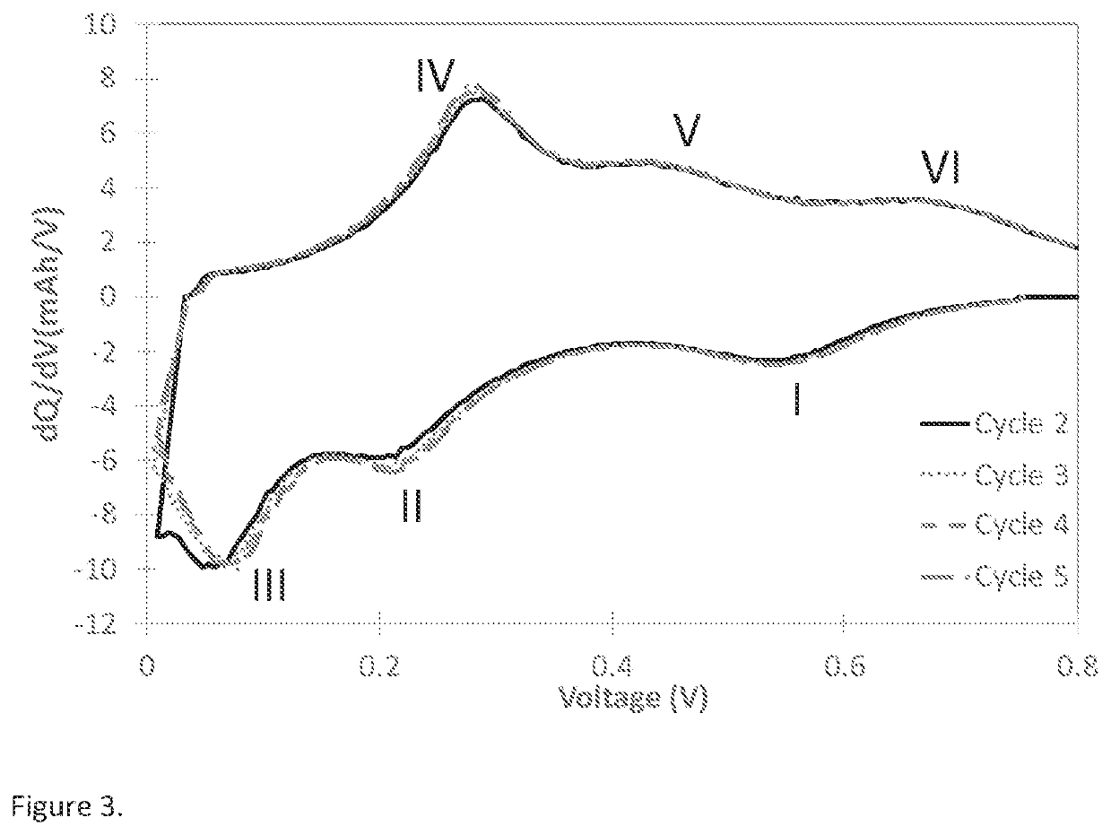
[0134]Differential capacity curve (dQ / dV vs Voltage) is often used as a non-destructive tool to understand the phase transition as a function of voltage in lithium battery electrodes (M. N. Obrovac et al. Structural Changes in Silicon Anodes during Lithium Insertion / Extraction, Electrochemical and Solid-State Letters, 7 (5) A93-A96 (2004); Ogata, K. et al. Revealing lithium-silicide phase transformations in nano-structured silicon-based lithium ion batteries via in situ NMR spectroscopy. Nat. Commun. 5:3217). As an alternative methodology to plotting dQ / dV vs Voltage, a strategy to yield similar analysis is the plot of dQ vs V. For this example, the differential capacity plot (dQ / dV vs Voltage) is calculated from the data obtained using galvanostatic cycling at 0.1 C rate between 5 mV to 0.8V in a half-cell coin cell at 25° C. Typical differential capacity curve for a silicon-based material in a half-cell vs lithium can be found in many literature ...

example 4

Size Distribution for Various Carbon Scaffold Materials

[0165]The particle size distribution for the various carbon scaffold materials was determined by using a laser diffraction particle size analyzer as known in the art. Table 7 presented the data, specifically the Dv,1, Dv10, Dv50, and Dv,90, and Dv,100.

TABLE 4Properites of various carbon scaffold materials.Carbon Scaffold#Particle Size Characteristics1Dv, 1 = 1.2 um, Dv, 10 = 2.5 um, Dv, 50 = 6.9 um,Dv90 = 11.5 um, Dv100 = 20.1 um2Dv, 1 = 1.09, Dv10 = 3.4 um, Dv50 = 7.67 um,Dv, 90 = 13.3 um, Dv100 = 17.84Dv, 1 = 0.81, Dv10 = 1.9 um, Dv50 = 6.4 um,Dv, 90 = 16.6 um, Dv100 = 26.55Dv, 1 = 0.62, Dv10 = 1.1 um, Dv50 = 4.2 um,Dv, 90 = 15.8 um, Dv100 = 29.88Dv, 1 = 1.3, Dv10 = 3.7 um, Dv50 = 16 um,Dv, 90 = 35.2 um, Dv100 = 50.79Dv, 1 = 1.2 um, Dv, 10 = 2.7 um, Dv, 50 = 7.6 um,Dv, 90 = 12.3 um, Dv100 = 20.7 um


PUM

PropertyMeasurementUnit
porosityaaaaaaaaaa
operating voltageaaaaaaaaaa

Abstract

Disclosed herein is an improved lithium-silicon battery. The anode of the battery comprises a composite comprising Group14 elements silicon and carbon. This composite comprises silicon in the preferred form for use in the lithium-silicon battery: silicon that is amorphous, nano-sized, and entrained within porous carbon. Compared to batteries found in the prior art, lithium-silicon batteries disclosed herein comprising the composite anode material disclosed herein find superior utility in various applications.

Description

BACKGROUNDTechnical Field[0001]Embodiments of the present invention generally relate to lithium-silicon batteries comprising a carbon and silicon containing anode material.Description of the Related Art[0002]Lithium-silicon battery is a name used for a subclass of lithium-ion battery technology that employs a silicon-based anode and lithium ions as the charge carriers. Silicon based materials generally have a much larger specific capacity, for example 3600 mAh / g for pristine silicon, relative to graphite, which is limited to a maximum theoretical capacity of 372 mAh / g for the fully lithiated state LiC6. Silicon's large volume change (approximately 400% based on crystallographic densities) when lithium is inserted is one of the main obstacles along with high reactivity in the charged state to commercializing this type of anode. Prior to this disclosure, performance of lithium-silicon batteries has been limited by inferior forms of silicon in the anode.[0003]To this end, there is cont...

Claims


Application Information

Patent Timeline
Patent Type & Authority Applications(United States)
IPC IPC(8): H01M4/36H01M4/38H01M4/587H01M10/0525H01M4/62H01M10/0567
CPCH01M4/364H01M4/386H01M4/587H01M2004/027H01M4/625H01M10/0567H01M10/0525H01M2004/021H01M4/362H01M4/133H01M4/134H01M2010/4292H01M10/0568H01M10/0569Y02E60/10H01M2300/0025
Inventor DHANABALAN, ABIRAMISAKSHAUG, AVERY J.COSTANTINO, HENRY R.
Owner GRP 14 TECH INC
Learn More