
Process using catalytic composition for the conversion of syngas to higher alcohols

Active Publication Date: 2022-03-24
TOTAL SE +1
View PDF0 Cites 0 Cited by
  • Summary
  • Abstract
  • Description
  • Claims
  • Application Information

AI Technical Summary

Benefits of technology

The present patent provides a new process for converting syngas to C2+ alcohols using a catalyst composition and one or more acidic materials. The process allows for improved conversion of CO to alcohols with higher yields and limited production of CO2, methanol, and DME. The catalyst composition comprises an active phase comprising CuFe deposited on a carbon-containing support, with the total content of iron and copper ranging from 1 to 10 wt. % based on the total weight of the catalyst composition. The carbon-containing support can be selected from carbon nanofibers and carbon nanotubes, with a hollow-core structure and inner diameter of at least 17 nm. The catalyst composition can further include one or more promoters such as alkali and alkaline earth metals, preferably potassium. The process allows for high yield in alcohols and improved selectivity towards alcohols with a CO conversion rate of 4% and a methanol production rate of 3% or less. The carbon-containing support should have a hollow-core structure with an inner diameter of at least 17 nm. The catalyst composition should have a ratio of carbon nanofibers to carbon nanotubes ranging from 80 wt. % to 99.9 wt. % and a Si / Al molar ratio ranging from 2 to 200 as determined by N2 sorption analysis. The process provides a new way to improve the conversion of CO to alcohols with higher yields and limited production of CO2, methanol, and DME.

Problems solved by technology

There is currently no commercially process for direct synthesis from syngas.
Work on this subject was initiated in the 1930s, however, has fluctuated with oil prices.
To date, no catalytic system reported has performed sufficiently well to justify an industrial implementation.
The majority of catalytic systems contain high loadings of their active metals, which limits their economic viability.
A number of Rh-based systems exist but their use is limited due to their high price.

Method used


Image

  • Process using catalytic composition for the conversion of syngas to higher alcohols
  • Process using catalytic composition for the conversion of syngas to higher alcohols

Examples


example 1

lysts Preparation

[0254]Bulk Catalyst

[0255]A bulk Cu—Fe catalyst with nominal molar Cu / Fe=2 was prepared by co-precipitation using Na2CO3 as the precipitating agent. Cu(NO3)2.3H2O (5.283 g, Aldrich Fine Chemicals, 98-103%) and Fe(NO3)3. 9H2O (4.406 g, Aldrich Fine Chemicals, >98%) were dissolved simultaneously in deionised water (65.6 cm3) yielding a solution with a total metals concentration of 0.5 M. The mixture was magnetically stirred at 343 K while adding a 0.5 M Na2CO3 solution (81-83 cm3, 2 cm3 min−1) to reach a pH of 8. The slurry obtained was aged for 3 h, washed with water (3 dm3), dried at 343 K, calcined at 723 K, and reduced in a 10 vol. % H2 / He flow of 20 cm3 min−1 for 4 h at 673 K (ramp rate=3 K min−1).

[0256]Supported Catalysts

[0257]Supported Cu—Fe catalysts with nominal molar Cu / Fe molar ratios of 1, 2, 3, or 5, and a Cu—Fe loading of 5 wt. % were prepared by a sol-gel method (SG). K was added as a promoter to the materials with Cu / Fe=2 in a nominal molar K / Cu—Fe mola...

example 2

K Promotion on CNF-Supported Cu—Fe Catalysts

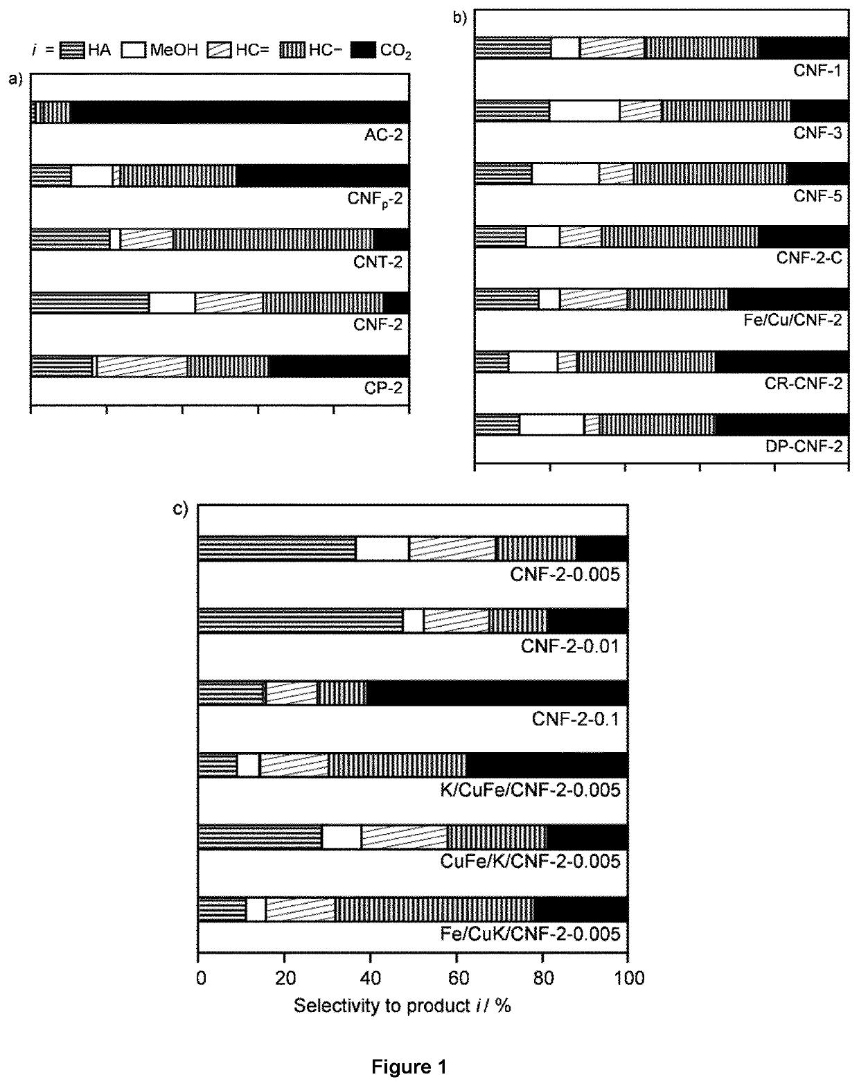
[0263]The impact of potassium as a promoter was studied on CNF-2. Three materials were prepared including different amounts of the alkali metal upon deposition of Cu and Fe so to reach nominal K / CuFe ratios of 0.005, 0.01 and 0.1. In addition, since the K loading is very small and falls below the detection limit of many characterisation techniques, it was attempted to gather insights into its role by varying the location and contact of this promoter with the active metals tailoring the synthesis method.

[0264]Hence, K was incorporated prior to or after the simultaneous deposition of Cu and Fe (CuFe / K / CNF-2-0.005 and K / CuFe / CNF-2-0.005) and along with Cu prior to Fe addition (Fe / CuK / CNF-2-0.005). The measured Cu / Fe ratio and Cu—Fe loading of the reduced catalysts were close to the nominal values (see Table 1), but the K loadings were systematically lower than expected, likely due to the presence of moisture in K2CO3.

[0265]When K was introduc...

example 3

terial

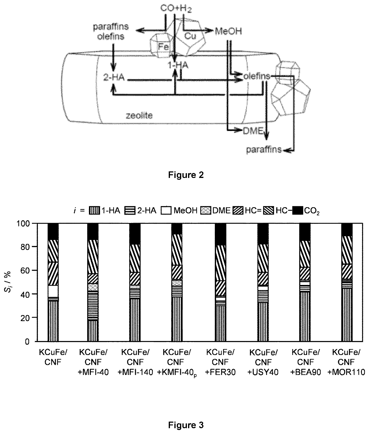
[0274]MFI zeolites with nominal Si / Al molar ratios of 40 and 140 (CBV8014 for 40 and CBV28014 for 140, Zeolyst Ltd., denoted as MFI-x, where x is the Si / Al molar ratio) and FER zeolites with nominal Si / Al molar ratio of 27.5 (CP 914, Zeolyst Ltd., denoted as FER30) were delivered in ammonium form and calcined as described above, to convert them into the corresponding protonic forms. MFI-40 samples partially (KMFI-40p) were obtained by treatments of the as-received MFI-40 in aqueous KNOB (1.0 mM and 0.1 M, respectively, 10 gzeolite dm−3, 8 h). The zeolite recovered by filtration was washed with deionized water (1 dm3 gzeolite−1), dried, and calcined under the same conditions as for the other samples.

[0275]USY zeolites with nominal Si / Al molar ratio of 40 (CBV780, Zeolyst Ltd., denoted as USY40), BEA zeolites with nominal Si / Al molar ratio of 90.5 (HCZB150, Clariant, denoted as BEA90), and MOR zeolites with nominal Si / Al molar ratio of 110 (690HOA, TOSOH, denoted as MOR110) were...


PUM

PropertyMeasurementUnit
Temperatureaaaaaaaaaa
Pressureaaaaaaaaaa

Abstract

The present disclosure relates to a process for converting syngas to C2+ alcohols, said process comprising the steps of providing a reactor, of providing a catalyst composition and one or more acidic materials within said reactor, of providing a feed stream comprising a mixture of H2 and CO; and of contacting said feed stream with said catalyst composition and said one or more acidic materials under reaction conditions to provide product stream. Said process is remarkable in that said catalyst composition comprises an active phase comprising CuFe deposited on a carbon-containing support, and the one or more acidic materials are one or more zeolites having a Si / Al molar ratio ranging between 2 and 200.

Description

FIELD OF THE DISCLOSURE[0001]The present disclosure relates to a process for converting syngas to higher alcohols using catalytic composition.BACKGROUND OF THE DISCLOSURE[0002]Syngas conversion is well known for producing a variety of chemicals including methanol, alkenes, alkanes. Such products are produced commercially as the methanol synthesis process or the Fischer-Tropsch synthesis (FTS) process. Higher alcohols (C2+) are important compounds with widespread applications in the chemical, pharmaceutical and energy sectors, for instance in the manufacture of pharmaceuticals, detergents, and polymers as well as alternative fuels, gasoline additive and hydrogen carriers. Currently, they are mainly produced by sugar fermentation (ethanol and isobutanol) or hydration of petroleum-derived alkenes. There is currently no commercially process for direct synthesis from syngas. Of the higher alcohols synthesis technologies described in the open literature, alcohol products are predominantly...

Claims


Application Information

Patent Timeline
IPC IPC(8): C07C29/156B01J23/745B01J21/18
CPCC07C29/156B01J21/185B01J23/745C07C31/02C07C31/08B01J21/14B01J23/70B01J23/74C07C29/151C07C29/153C07C29/154
Inventor CURULLA-FERRE, DANIELSTEWART, JOSEPHPEREZ-RAMIREZ, JAVIERMONDELLI, CECILIALUK, HO TING
Owner TOTAL SE
Learn More