Catalytic plasmonic nanomaterial

a plasmonic nanomaterial and catalytic technology, applied in physical/chemical process catalysts, metal/metal-oxide/metal-hydroxide catalysts, instruments, etc., can solve the problem of not being financially viable as currently implemented, lack of use discussion, and the limiting factor of current reactor activation energy, etc. problem, to achieve the effect of increasing reaction area and light harvesting

Pending Publication Date: 2022-06-23
HABIB TECH LLC
View PDF1 Cites 1 Cited by
  • Summary
  • Abstract
  • Description
  • Claims
  • Application Information

AI Technical Summary

Benefits of technology

[0017]The present invention provides for an optical reactor device that utilizes plasmonic catalytic nanomaterials for photocatalytic synthesis of fuels and chemicals including oxygenates like methanol, hydrocarbons like ethylene, or non-carbon compounds like ammonia, including a chemical reaction chamber containing catalytic plasmonic nanomaterial, the chemical reaction chamber including a gas distribution manifold for flowing gas containing reactive components over the catalytic plasmonic nanomaterial and a gas collection manifold for collecting synthesized gas products, wherein the chemical reaction chamber includes a mechanism of providing optical energy to the catalytic plasmonic nanomaterial through illumination and provides constant temperature control of the chemical reaction chamber.

Problems solved by technology

Many studies lack discussion about using CO2 as a feedstock for fuel production.
A rigorous lifecycle analysis of the impact and cost of industrial methanol synthesis from CO2 feedstock in these production scale systems concluded that while the present technologies do lead to a significant net CO2 emission reduction; they are not financially viable as currently implemented.
The limiting factor in current reactors is the activation energy required to reduce carbon dioxide.
However, the high-temperature (˜400-500° C.) and high-pressure (˜150-250 Bar) requirements of the process make it energetically highly inefficient.

Method used


Image

  • Catalytic plasmonic nanomaterial
  • Catalytic plasmonic nanomaterial
  • Catalytic plasmonic nanomaterial

Examples


example 1

Fabrication and Characterization of Plasmonic Nanomaterials

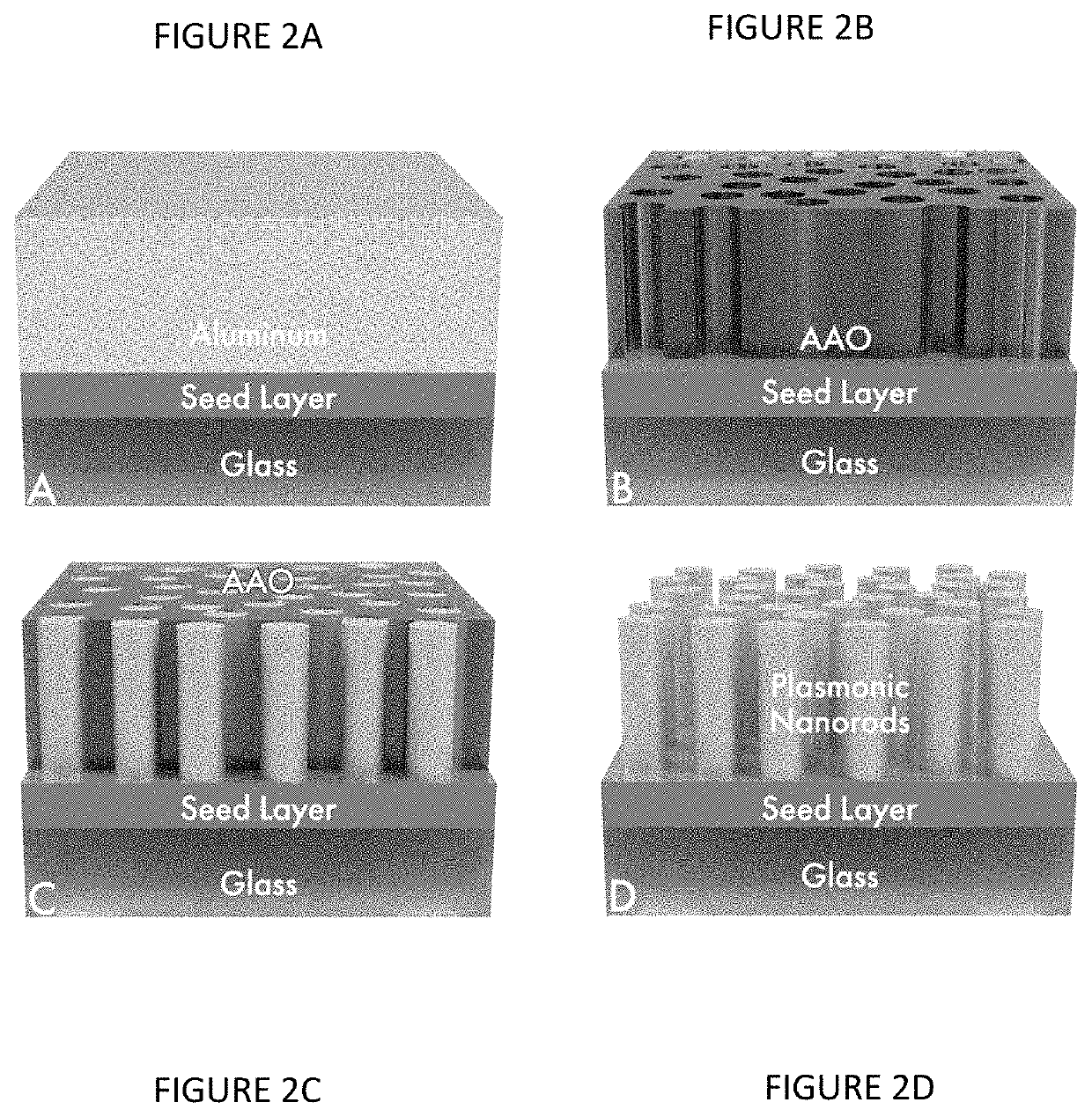
[0122]Silver plasmonic nanomaterial samples are prepared on 50 mm×50 mm coupons of CORNING® WILLOW® Glass. The coupons are first coated with a 10-30 nm Ti adhesion layer, followed by a 20-50 nm Ag layer and then an Al layer of 200-800 nm thick. The deposition is performed via sputter and / or e-beam evaporation under ultra-high vacuum. The coated coupons are then mounted in an electrochemical immersion process cell which is used to make electrical contact using a pogo-probe and O-ring assembly and carry the sample through the anodization and electroplating steps of the nanofabrication process. The pogo probe allows ease of handling as the samples are electrochemically processed with minimal contact area.

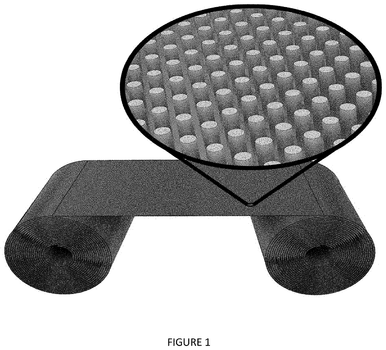
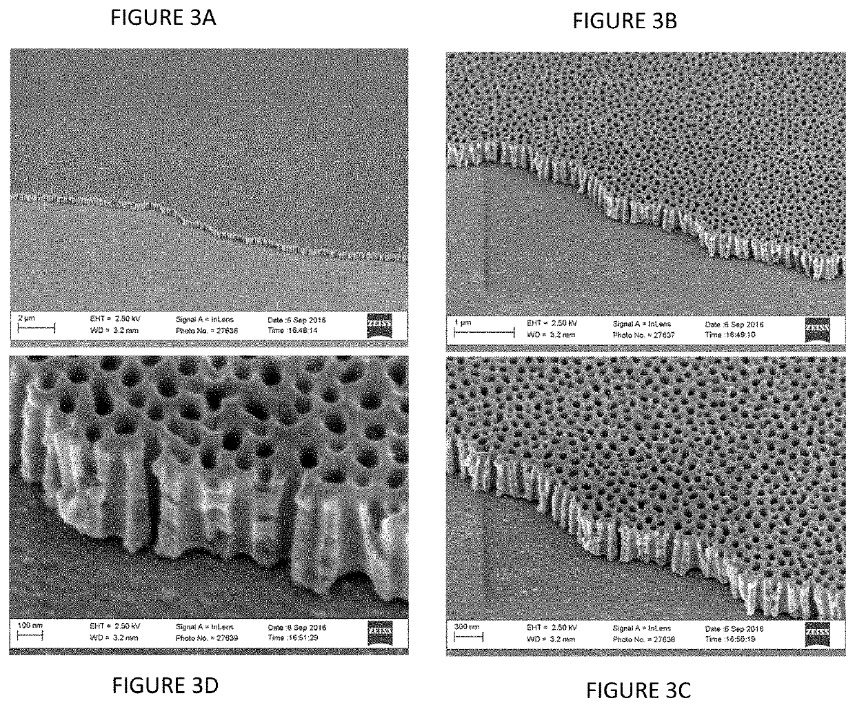
[0123]The plasmonic nanomaterial is fabricated on coated glass by first completely anodizing the Al layer and forming a nanoporous AAO template used for nanorod array synthesis. It is well established that the electrochemical o...

example 2

Catalytic Activation of Silver Plasmonic Nanorod Arrays

[0126]Cu—Pd bimetallic catalysts have greater CH3OH formation rates than either Cu or Pd monometallic catalysts exhibit and are effective at promoting the reaction CO2+2H2→CH3OH. The preparation of a stoichiometrically controlled bimetallic layer on the nanorod surfaces can be performed with varying the coverage of the Cu—Pd bimetal. By controlling the surface stoichiometry of Cu and Pd on the Ag nanostructures, optimal formulations of bifunctional, bimetallic catalysts can be prepared. The Pd sites provide active locations for the dissociative adsorption of H2, while the adjacent, or vicinal Cu sites, promote dissociative adsorption of CO2 to form adsorbed CO and oxygen species, which subsequently undergo facile reduction to form CH3OH and H2O as products. In the present invention, a bimetallic layer is applied to the silver nanorod arrays to catalytically activate the plasmonic nanomaterial. Such coated nanorods are represente...

example 3

Photocatalytic Synthesis of CH3OH from CO2 and H2 Using Optical Flow Reactor

[0129]An optical flow reactor design that utilized for the light induced synthesis of methanol from CO2 and H2 via the present catalytic plasmonic nanomaterial invention is shown in FIG. 15. This is a continuous gas-phase flow-reactor design incorporating feed and product sampling and analysis. The volume of the reaction vessel volume is 50 mL and it accommodates two 50×50 mm square coupons of the catalytic plasmonic nanomaterial. It has a low-profile bed for short residence time short, i.e. 30 seconds at 100 sccm flow (standard cubic centimeters per minute). The system is mounted in a heating mantle to be used as needed, although optical power from the LED array is the primary driver in the reaction.

[0130]Regarding the present invention, the catalytic plasmonic nanomaterial can be used in a flow reactor 10, such as one represented in FIG. 15, such as for synthesis of methanol, ammonia, or other products. Fl...


PUM

PropertyMeasurementUnit
lengthsaaaaaaaaaa
lengthsaaaaaaaaaa
diametersaaaaaaaaaa

Abstract

A method for producing plasmonic nanomaterials that are catalytically or photocatalytically active by fabricating plasmonic nanostructures on substrates using electrodeposition into a nano-template structure and forming a plurality of nanorods in an array, wherein the nanorods are made from materials chosen from the group consisting of materials that are plasmonic and / or catalytic, and materials that are catalytically activated by depositing pure elemental metals, alloys, or alternating layers of different metals or alloys, and producing catalytic plasmonic nanomaterials. Catalytic plasmonic nanomaterials made from the above method. An optical reactor device that utilizes catalytic nanomaterials for photocatalytic synthesis of methanol or ammonia. A method of photocatalytic synthesis of methanol and ammonia by using catalytic plasmonic nanomaterial to convert CO2 and H2 to methanol and N2 and H2 to ammonia using optical power. A hybrid plasma-plasmonic reactor for the utilization of CO2 and CH4 to produce methanol, ethylene, and acetic acid.

Description

GRANT INFORMATION[0001]Research in this application was supported in part by grants from the US Department of Energy Chicago Office and the US Department of Energy Office of Science (Grant No. DE-SC0015942 and DE-SC0019657). The Government has certain rights in the invention.BACKGROUND OF THE INVENTION1. Technical Field[0002]The present invention relates to plasmonic nanostructures. More specifically, methodologies for the fabrication and manufacture of catalytically active plasmonic nanostructures are disclosed, as are techniques to utilize these nanomaterials for photocatalysis and chemical synthesis. The nanomaterial invention interacts with electromagnetic radiation (light) generating plasmonically-induced heat and energetic carriers (hot electrons and holes) that are utilized to facilitate chemical reactions. The invention is in the technical field of fabricating catalytic plasmonic nanomaterials and applications thereof.2. Background Art[0003]According to the U.S. Department o...

Claims


Application Information

Patent Timeline
Patent Type & Authority Applications(United States)
IPC IPC(8): B01J23/89B01J21/06B01J23/50B01J21/02B01J35/00B01J35/04B01J37/34B01J37/02B01J15/00B01J19/12B01J19/00C01C1/04C07C31/04C07C29/157
CPCB01J23/8926B01J2219/0875B01J23/50B01J21/02B01J35/004B01J35/0013B01J35/04B01J35/0033B01J37/348B01J37/0225B01J37/0244B01J37/0228B01J15/00B01J19/127B01J19/006C01C1/0417C01C1/0411C07C31/04C07C29/157B01J2219/00763B01J2219/1203B01J2219/0892B01J21/063G02B5/008B01J23/48B01J37/06B01J23/24B01J37/347B01J35/026B01J35/023B01J35/06B01J23/72B01J23/74B01J23/34B01J23/08B01J23/42B01J23/44B01J23/464B01J23/06B01J23/468B01J35/008B01J37/0238B01J2219/00045B01J8/0285B01J8/067B01J19/123B01J19/1812B01J19/2415B01J19/32B01J2208/00451B01J2208/00433B01J2219/00144B01J2219/00139B01J2219/24B01J2219/0898B01J2219/0845B01J2219/0809B01J2219/00162B01J2219/32248B01J2219/32279B01J2219/32466B01J19/088B01J2219/0835
Inventor HABIB, YOUSSEF M.ULMAN, ABRAHAM
Owner HABIB TECH LLC
Why Eureka
Try Eureka