Eureka AIR delivers breakthrough ideas for toughest innovation challenges, trusted by R&D personnel around the world.

Electroplating systems and methods for wear-resistant coatings

Pending Publication Date: 2022-11-03
HONEYWELL INT INC
View PDF6 Cites 0 Cited by
  • Summary
  • Abstract
  • Description
  • Claims
  • Application Information

AI Technical Summary

Benefits of technology

The patent describes an electroplating system which includes a tank with an anode, a cathode, and an electrical connection for providing electric current. The system also includes a supply line for delivering electrolytic fluid to the tank. The patent also describes a method for electroplating a component part by introducing the component part into the tank with the electrolytic fluid and applying an electroplating current to the component part and the anode. The technical effect of the patent is to provide an efficient and effective system for electroplating components in a simple and straightforward manner.

Problems solved by technology

Such legacy wear resistant coatings are, however, typically limited in one or more respects.
For example, the High Velocity Oxygen Fuel (HVOF) deposition processes utilized to deposit WC coatings are often costly to perform.
Further, in the case of both hard chrome platings and WC coatings, such coatings are typically quite hard and brittle as initially deposited.
As a result, such legacy wear resistant coatings pose additional challenges when machining is desirably performed following coating deposition to define structural features, to satisfy dimensional tolerances, or meet surface finish requirements.
Post-coating machining, such as grinding to satisfy surface finish requirements, is thus a costly and time-consuming process, often requiring diamond cutting tools and specialized operations.
Post-coating machining can also potentially result in damage, such as chipping or cracking, of the newly-deposited wear resistant coating.
This may not only adversely impact the structural integrity of the wear resistant coating, but may also render the coating prone to the ingress of environmental contaminants as noted above.
Such rotor sections for the oil and gas industry may range from about 2 to about 30 feet long and have a complex geometry and material handling difficulty.
Conventionally, components are plated vertically in open electroplating tanks, which are costly to install.
Open vertical electroplating tanks require high ceilings, and the risk of gas evolution and tank leakage is high.
Furthermore, maintenance of vertical tanks is labor intensive and causes significant downtime, and rotation of parts in vertical electroplating tanks is not feasible.
Heavy parts must be transferred from one tank to another between process steps, which increases processing time and creates safety and quality concerns due to instability of the part during transfer.
This results in possible over-plating of the peaks, which then need costly grinding to be performed.

Method used

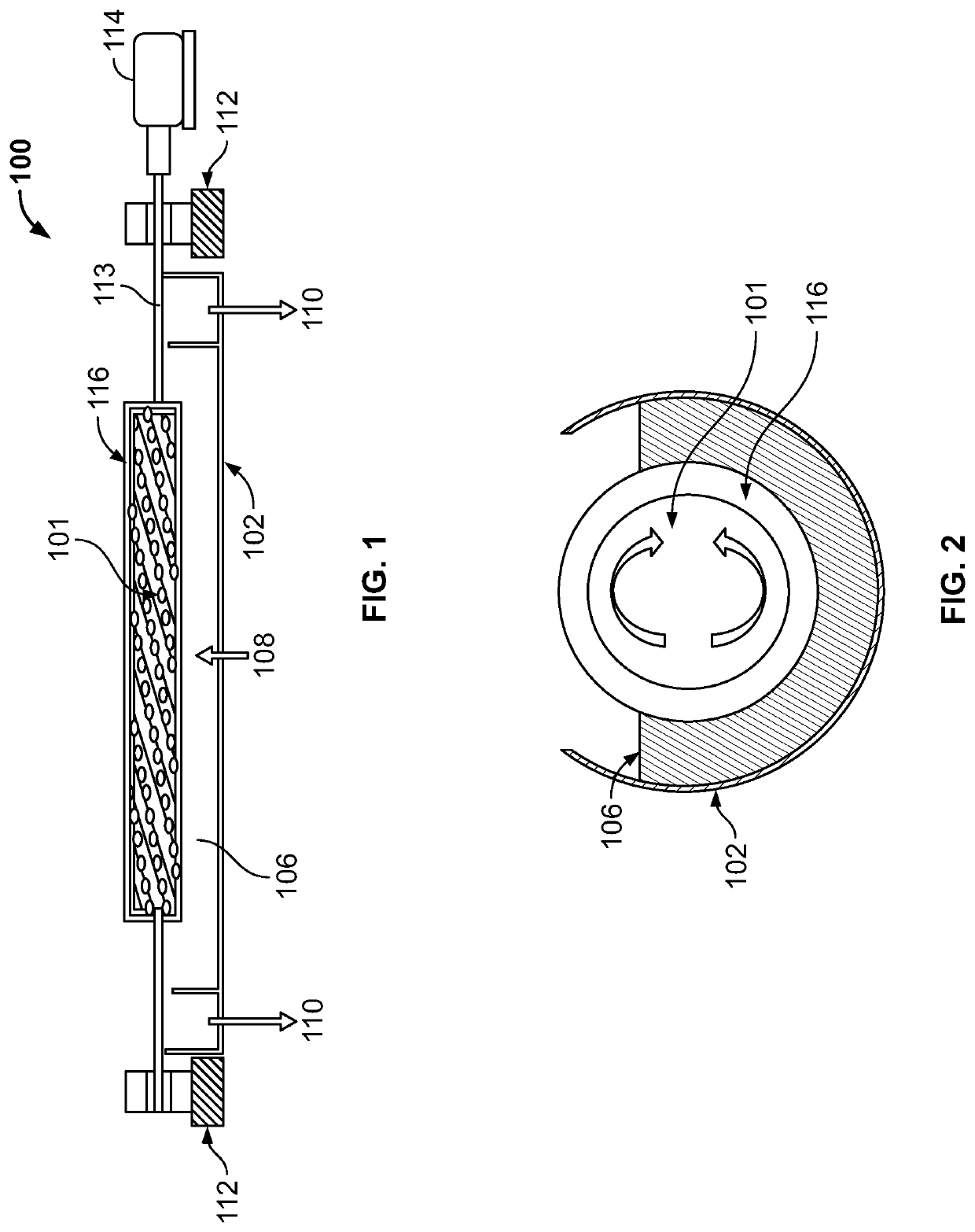
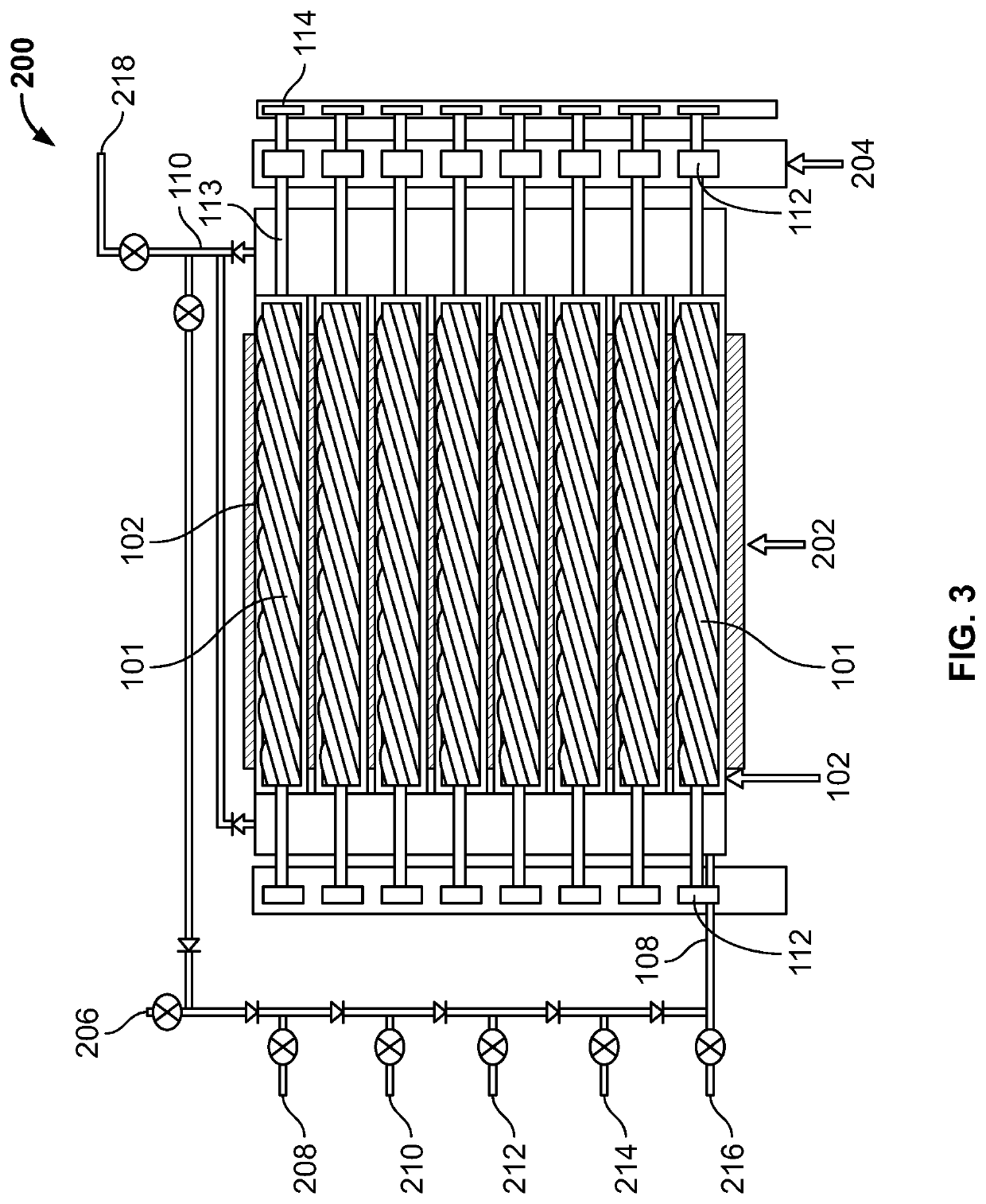
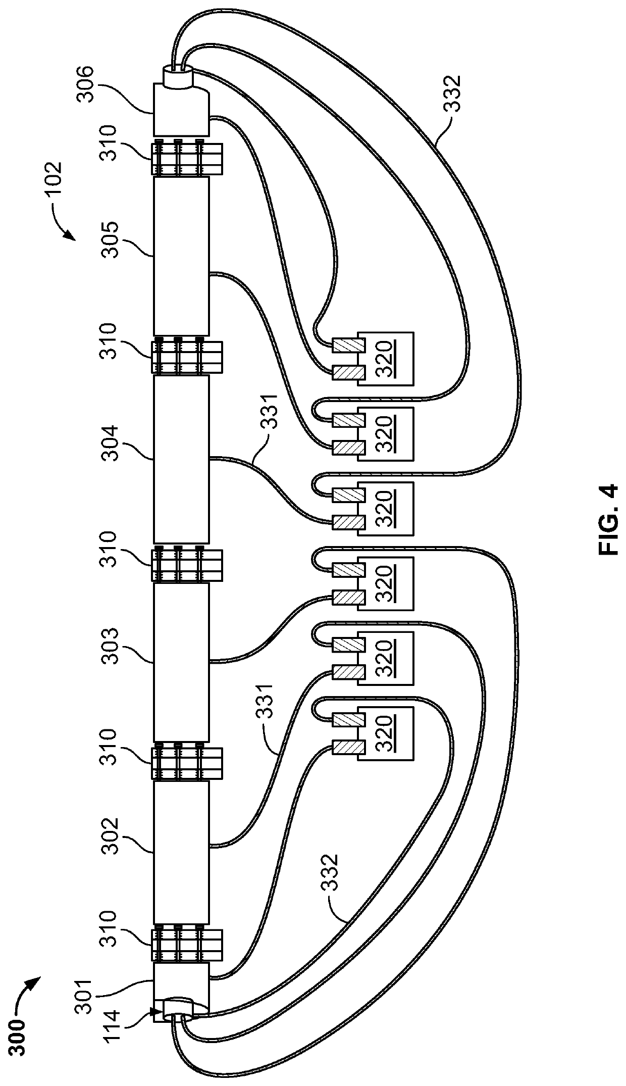

Image

  • Electroplating systems and methods for wear-resistant coatings
  • Electroplating systems and methods for wear-resistant coatings
  • Electroplating systems and methods for wear-resistant coatings

Examples


Embodiment Construction

[0016]The following detailed description is merely exemplary in nature and is not intended to limit the invention or the application and uses of the invention. As used herein, the word “exemplary” means “serving as an example, instance, or illustration.” Thus, any embodiment described herein as “exemplary” is not necessarily to be construed as preferred or advantageous over other embodiments. All of the embodiments described herein are exemplary embodiments provided to enable persons skilled in the art to make or use the invention and not to limit the scope of the invention which is defined by the claims. Furthermore, there is no intention to be bound by any expressed or implied theory presented in the preceding technical field, background, brief summary, or the following detailed description.

[0017]Unless specifically stated or obvious from context, as used herein, the term “about” is understood as within a range of normal tolerance in the art, for example within 2 standard deviatio...


PUM


Abstract

An electroplating system includes a tank functioning as an anode, wherein the tank is configured in a horizontal orientation having a length greater than its height, a component part disposed within the tank and functioning as a cathode, an electrical connection, coupled to the anode and cathode, for providing an electric current, and a supply line for delivering an electrolytic fluid to within the tank.

Description

CROSS-REFERENCE TO RELATED APPLICATIONS[0001]This application claims the benefit of U.S. Provisional Application No. 63 / 180,976, filed Apr. 28, 2021, the contents of which are herein incorporated by reference in their entirety.TECHNICAL FIELD[0002]The following disclosure relates generally to electroplating systems to produce wear resistant coatings, as well as to methods for the formation of such wear resistant coatings.BACKGROUND[0003]There is a need for low cost, high performance wear resistant coatings across various industries. In the oil and gas industry, for example, there exists a continued demand for wear resistant coatings suitable for deposition over components utilized in downhole drilling applications, such as lobed rotor shafts of the type found in the power section of steerable and non-steerable downhole mud rotors. Ideally, such wear resistant coatings are relatively durable and possess high hardness values exceeding, for example, 900 Vickers Pyramid Number (HV). It ...

Claims


Application Information

Patent Timeline
IPC IPC(8): C25D17/00C25D17/02C25D17/12
CPCC25D17/008C25D17/02C25D17/12C25D17/16C25D5/00C25D5/34C25F3/00C25D21/18C25D21/10C25D3/12C25D7/00C25F1/00C25F7/00
Inventor SKLAR, GLENNPIASCIK, JAMESMINTZER, JOSEPH
Owner HONEYWELL INT INC
Why Eureka
Eureka Blog
Learn More