Bright metal flake

a metal flake and bright technology, applied in the field of bright metal flake, can solve the problems of affecting the reflective properties of the application, affecting the performance of the flakes, and affecting the spectra of the flakes, and achieve good specular reflectance characteristics

Inactive Publication Date: 2000-01-11
JDS UNIPHASE CORP
View PDF23 Cites 168 Cited by
  • Summary
  • Abstract
  • Description
  • Claims
  • Application Information

AI Technical Summary

Benefits of technology

It is, therefore, an object of the present invention to provide a substantially rigid thin metal flake having good specular reflectance characteristics in the wavelength range of about 300 to about 800 nm.

Problems solved by technology

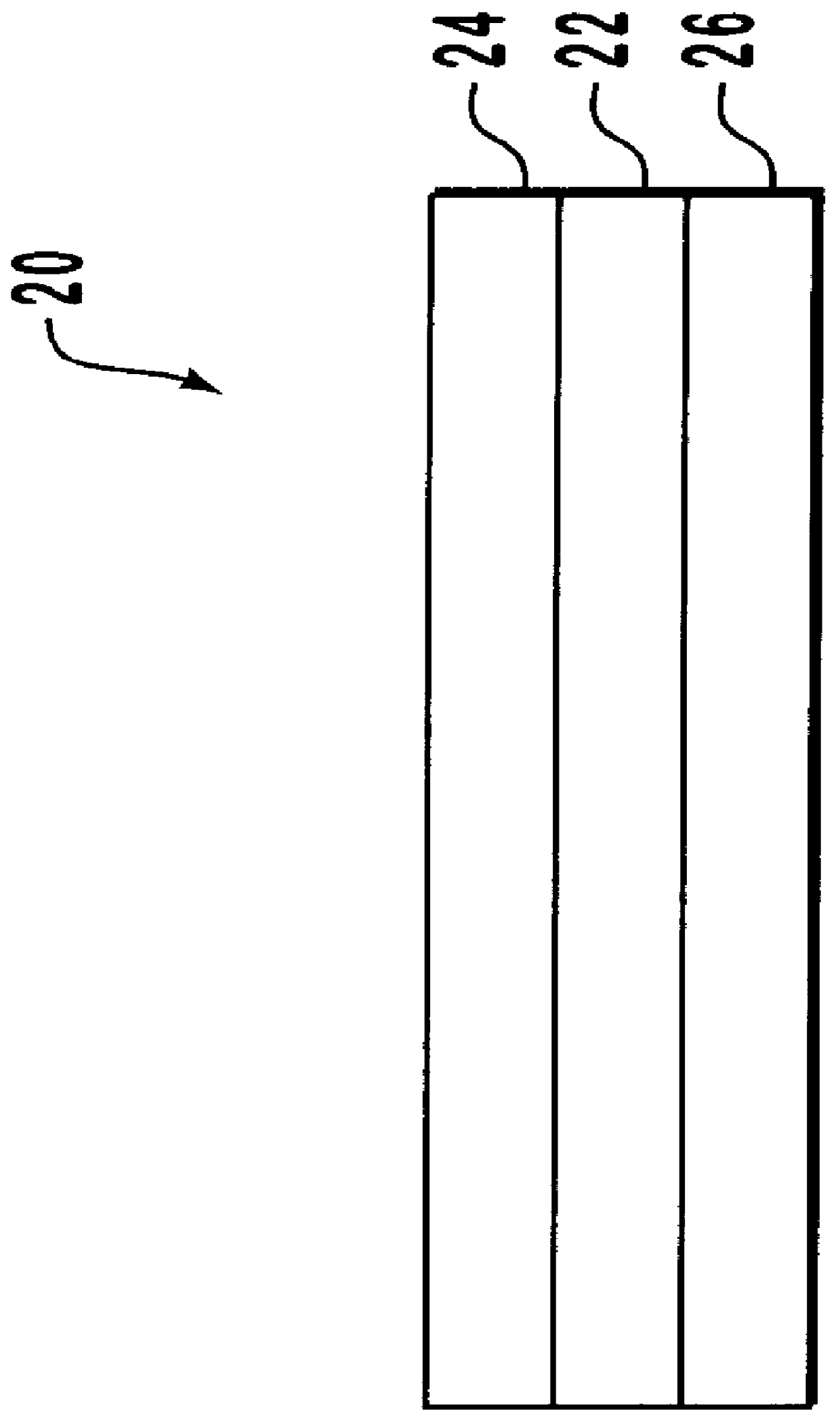
A major factor, however, affecting those reflectance characteristics is the size or dimensions of the flake as the flake is used in a particular application.
As a result, many flakes are adversely caused to be oriented in a substantially vertical manner and the plurality of flakes are formed into a radically non-planar layer.
Incident light then exposed upon the non-planar layer is subject to extreme scatter and diffraction.
Thus, the favorable reflective properties of the application are diminished by thick flakes.
To a lesser extent, thick flakes frequently cause other difficulties such as the clogging of automatic-spray paint guns during painting applications.
However, it is also well known that as the thicknesses of the flakes is reduced, the point is reached where the flakes become so flimsy (non-rigid, flaccid) that they begin to curl and / or wrinkle.
This decreases favorable planarity and reflective properties because incident light exposed upon the flakes is subject to scatter and diffraction.
Additionally, if the flakes are too thin when applied onto a surface during applicational use, the flakes will assume any microscopic defects in the contour of that surface.
Again, disfavored planarity and reflective properties result because incident light exposed on the surface is subject to scatter and diffraction.
Two types of fracture may result, "ductile" or "brittle."
This deformation causes numerous malformed regions having disfavorable planar characteristics to appear.
As before, these malformed regions, such as regions having curled or wrinkled metal, disadvantageously tend to scatter and diffuse incident light exposed thereupon.
Consequently, brittle fracture is the desired manufacturing fracture means.
In fact, brittle fracture is only likely to occur with materials having a large compressive strength as compared to its corresponding tensile strength.
Consequently, a high compressive strength relative to tensile strength results in bond rupture and material cracking when a force is applied.
Moreover, once the aluminum is bent or deformed, as would occur with ductile fracture, the aluminum remains deformed and the disfavored reflective characteristics would persist.
Consequently, it is difficult to manufacture metal flakes, such as aluminum, without malformations that reduce reflectance.
For example, applicational processes, such as the drying of a paint or ink solvent, also induce stresses on the flake.
These stresses, caused by surface tension, again cause the flake to undergo fracture or malformation.
Yet all prior solutions have involved compromises.
Alloying, however, dilutes the reflectance properties of the flake.
Such compatibility is difficult and has not proved to be practical.
Such attacks primarily include corrosion which not only corrodes the flake but tends to give the application a mottled or discolored appearance.
Additionally, if this method were used in conjunction with another resinous application, such as a clear overcoat paint, the overcoat itself would tend to disfavorably disrupt the planar orientation of the flake because of solvent penetration.
A shrinking aspect ratio, however, also correspondingly shrinks the inherent reflectance capability of the flake.
Whenever an oxide is used, however, the inherent reflectance properties of the flake are decreased.
Additionally, oxides are typically formed at defect sites on the flakes which then tends to prevent a uniform application across the surface of the flake.
This non-uniformity introduces a reduction in reflectance and can also cause a mottled applicational appearance.
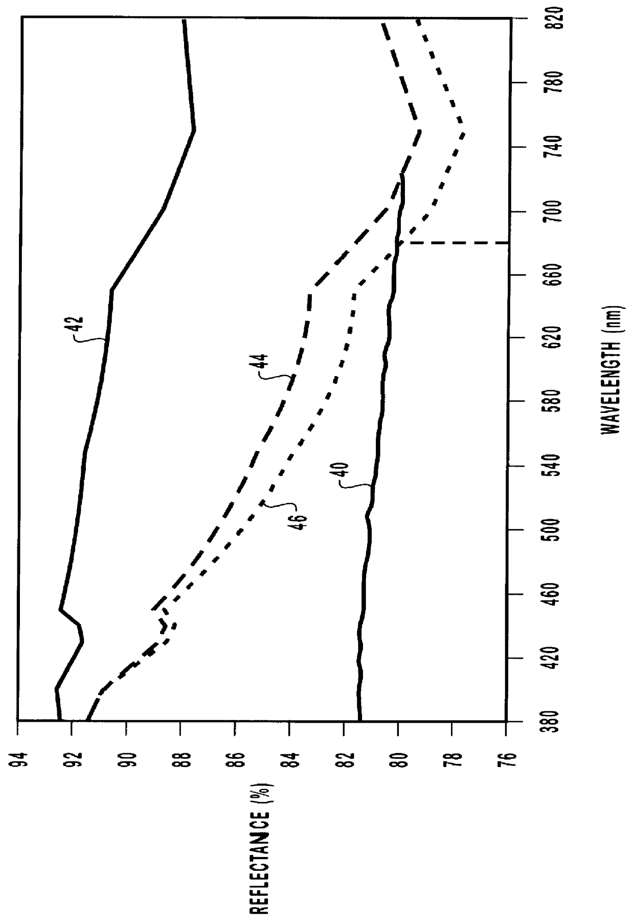
Thus far, the singular layer coatings have been so thick that reflective properties are detrimentally damaged because the coatings have greatly contributed to the scatter of light.
The multiple layer coatings have induced even more scatter and adversely caused light to diffuse at the boundaries between various layers.
In addition, all coatings thus far have essentially been organic and inherent within the crystalline structure of these organic coatings is a natural limitation as to how thinly applied the coatings can be manufactured and still provide structural rigidity to a flimsily thin metal flake.
Disadvantageously, the natural thickness limitation is still so large that other applicational processes remain burdened by this thickness.
Moreover, organic coatings when applicationally used in a solvent are eventually caused to lose structural rigidity because of dissolution related effects.
Although some reflective coatings exist that are rigid and facilitate brittle fracture, the coatings are unlike most of the other prior art because they do not even use a metal flake.
Although rigid and subject to brittle fracture, this structure is typically very thick (about 215 microns) and cannot be used in many applications requiring thin flakes.
But as thicknesses and layers increase, manufacturing complexities and economic burdens correspondingly increase.

Method used


Image

  • Bright metal flake
  • Bright metal flake

Examples


Embodiment Construction

Several samples of applicational pigments were prepared, each sample containing a plurality of bright metal flakes in accordance with the present invention. The metal layers each had a thickness of about 100 nm of aluminum and ranged in diameter from about 1 to about 50 microns. Layered upon the opposing planar surfaces of the metal layer was an inorganic dielectric coating having a thickness in a range of about 100 to about 200 nm. The inorganic dielectric coatings were selected as either silicon dioxide or magnesium fluoride.

With reference to FIG. 2, the actual reflectance results obtained as a function of various wavelengths were observed and recorded as reflectance curve 40. The reflectance curve has also been empirically supported by the results obtained from various other measurement devices (not shown) such as ink drawdowns, paint sprayouts and microscopy.

Super-imposed with the reflectance curve 40 on the reflectance-wavelength graph in FIG. 2 is the actual reflectance curve ...


PUM

PropertyMeasurementUnit
thicknessaaaaaaaaaa
thicknessaaaaaaaaaa
aspect ratioaaaaaaaaaa

Abstract

A rigid and brittle bright metal flake is formed of a central layer of a reflective material supported on both sides by dielectric layers. In a preferred embodiment, the metal layer is aluminum having a thickness of about 100 nm and the dielectrics are either silicon dioxide or magnesium fluoride, each having a thickness of about 100 nm. The result is a very thin three-layered metal flake about 300 nm thick that exhibits a uniaxial compressive strength of about 8 times a corresponding uniaxial tensile strength. As a result, the metal flake is then afforded the benefits of rigidity and brittle fracture during the manufacturing and applicational processes which ultimately provides favorable planar and specular reflectance characteristics in the visible wavelength range.

Description

1. The Field of the InventionThe present invention relates generally to metal flakes. More specifically the present invention relates to thin metal flakes useful as pigments.2. The Relevant TechnologyThe prior art is replete with various applications utilizing metallic flakes or platelets (hereinafter collectively referred to as flakes) to improve the luster, sparkle, shine, and / or reflective properties of the application. Such applications are well known and include coating compositions, inks, extrusions, paints, electrostatic coatings, infrared interference pigments, glass, ceramics and cosmetics. In general, it is known that for the application to achieve the greatest specular reflectance across visible wavelengths (300-800 nm), the metallic flakes should individually lay as flat as possible. As a collection of numerous flakes, the greatest reflectance, and hence greatest brightness, occurs when the flakes are collectively planar oriented to expose the greatest amount of surface ...

Claims


Application Information

Patent Timeline
Patent Type & Authority Patents(United States)
IPC IPC(8): C09C1/00C09C1/62C09C1/64
CPCC09C1/0021C09C1/62C09C1/642C09C1/0015C01P2004/54Y10T428/264C09C2200/1054C09C2200/1058C09C2200/1087C09C2200/301C09C2200/302C09C2200/303Y10T428/257Y10T428/256Y10T428/266Y10T428/26Y10T428/2993Y10T428/265Y10T428/2991Y10T428/31678
Inventor COULTER, KENTMAYER, THOMASPHILLIPS, ROGER W.
Owner JDS UNIPHASE CORP
Why Eureka
Try Eureka