Biofilm assay

a biofilm and assay technology, applied in the field of biofilm assay, can solve the problems of biofilms causing problems in a variety of areas, wrong antibacterial reagent or wrong amount of antibacterial reagent for treatment, and may be used in different treatment directions. , to achieve the effect of improving the reliability of treatment of different projections and preventing contamination

Inactive Publication Date: 2000-04-18
UNIV TECH INT
View PDF15 Cites 34 Cited by
  • Summary
  • Abstract
  • Description
  • Claims
  • Application Information

AI Technical Summary

Benefits of technology

The biofilm assay device also includes a vessel 20 which includes a liquid holding basin 22 divided into plural channels (troughs) 24 by moulded ridges 26. The channels 24 are wide enough to receive the projections 12. There should be one channel 24 for each projection 12 of any given row 14. The lid 10 forms a support for the projections 12 for supporting the biofilm adherent sites within the channels 24. The lid 10 has a surrounding lip 16 that fits tightly over a surrounding wall 28 of the vessel 20 to avoid contamination of the inside of the vessel during incubation.
The biofilm incubation vessel 20 serves two important functions for biofilm development, The first is as a reservoir for liquid growth medium containing the bacterial population which will form a biofilm on the projections 12 of the biofilm lid 10. The second function is to generate shear force across the projections, which allows for optimal biofilm production on the projections.
As shown, in FIG. 4, shear force on the projections 12 is generated by rocking the vessel 20 with lid 10 on a tilt table 30. The projections 12 sit suspended in the channels 24, so that the tips of the projections 12 may be immersed in liquid growth medium flowing in the channels 24. The ridges 26 channel the liquid growth medium along the channels 24 past and across the projections 12, and thus generate a shear force across the projections. Rocking of the vessel 10 causes a repeated change in direction of flow, in this case a repeated reversal of flow of liquid growth medium, across the projections 10, which helps to ensure a biofilm of equal proportion on each of the projections 12 of the lid 10. While it is possible to grow biofilm with only one direction of flow of liquid growth medium, the use of an array of projections 12 suspended in several channels makes the arrangement difficult to construct, since then some method would need to be found to recirculate fluid around from one end of each channel to the other end. Rocking of the vessel, with liquid flowing backwards and forwards along the channels, provides an excellent biofilm growth environment that simulates natural occurring conditions of turbulent flow.
Sensitivity of a biofilm to antibiotic or biocide, referred to in this patent document collectively as "antibacterial reagent", is measured by treating the biofilm adherent sites with an anti-bacterial reagent, and then assaying the biofilm. This may be accomplished by placing the lid 10, which was colonized with a bacterial biofilm in an incubation vessel 12, into a conventional 96 well plate 40 such as illustrated in FIG. 5, the number of wells 42 being determined by the number of projections 12, in which growth medium containing antibiotic or biocide dilutions has been dispensed. The lid 10 and plate 40 fit such that bacterial contamination from outside the plate cannot take place. Projections 12 that have been incubated in the same channel 24 of the vessel 20 should each be treated with a different anti-bacterial reagent. In this manner, consistent results may be obtained since the growth conditions in any one channel will be very similar along the entire channel and thus for each projection 12 suspended in that channel. This helps improves the reliability of treatment of different projections 12 with different anti-bacterial reagents.
(1) Place 20 ml of a 2% overnight culture diluted in fresh growth medium (for example TSB) in the vessel 20 of the biofilm assay device system, cover with the biofilm lid 10 and incubate on the rocking platform 30, for example at 37.degree. C. for the time required to reach a biofilm of .about.10.sup.5 cfu / projection 12. Change of direction of flow of liquid growth medium caused by the rocking of the tilt table 30 enhances the growth of a biofilm.

Problems solved by technology

Biofilms may cause problems in a variety of areas including the bodies of humans and animals, food processing, health care facilities, metal-working shops, dairy fares and other industries.
Thus, bacterial inhibitory concentration of the antibacterial reagent may be underestimated, with the result that the wrong antibacterial reagent or wrong amount of antibacterial reagent may be used for the treatment of the bacteria.
Such devices as the Robbins device, or others using removable studs in a single conduit, result in rather lengthy processing times, and do not provide rapid response times for the testing of several different antibacterial reagents.
This method has the disadvantage of inconsistent colonization of sessile bacteria and settling of planktonic bacteria.

Method used


Image

  • Biofilm assay
  • Biofilm assay
  • Biofilm assay

Examples


example # 2

EXAMPLE #2

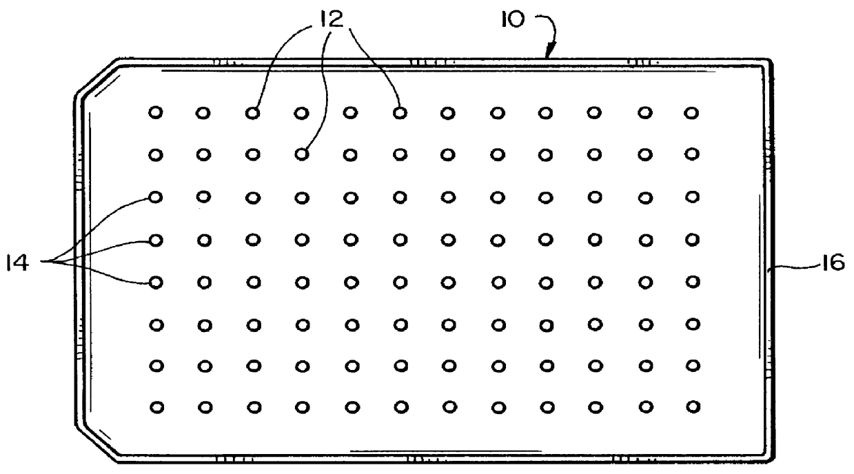
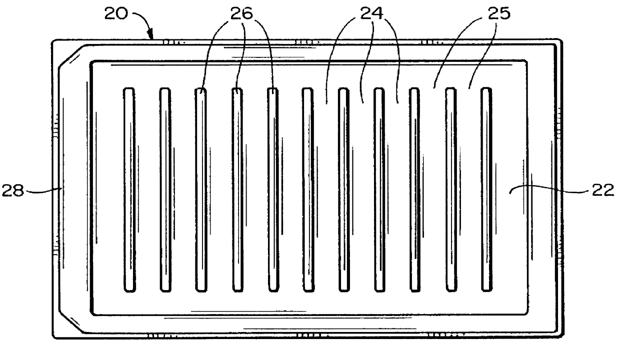
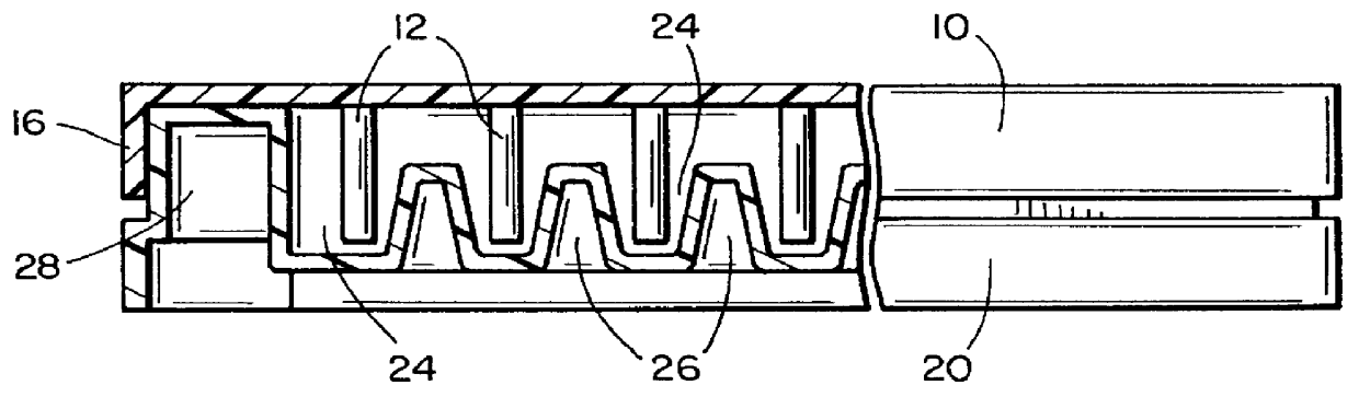
Table 4 shows the results of incubation of staphylococcus aureus biofilm on projections 12 in channels 24 while rocking the vessel 20, followed by treatment with antibiotics A (Ancef, cefazolin), B (Orbenin-2000, cloxacillin), C (Primaxin, imipenem and cilastatin), D (Vancomycin), E (Dalacin, clindamycin) F (Tazadine, ceftazidine) and G (Ciprofloxacin) in doubling dilutions. The antibiotic was applied to the wells 2-12 of the rows A-G of a 96 well plate as follows: well 2: no antibiotic, well 3: 1000 .mu.g / mL, well 4: 500 .mu.g / mL . . . well 12: 2 .mu.g / mL.

Table 5 shows the optical density readings of turbidity of the same staph. aureus biofilm, treated in the same manner as the samples of Table 4, to show a comparison between the manually counted cfu and the automated reading.

Table 6 shows the optical density readings of turbidity of staph. aureus planktonic bacteria incubated and treated with antibacterial reagent under the same conditions as for the results shown in Tab...

example # 3

EXAMPLE #3

Table 7 shows the results of incubation of Escherichia coli biofilm on projections 12 in channels 24 while rocking the vessel 20, followed by treatment with antibiotics A (Ticarcillin, Sigma T-5639), B (Carbenicillin, Sigma C-1389), C (Tobramycin, Sigma T-4014), D (Gentamicin sulphate, Sigma G-3632), E (Ampicillin, Sigma A-9518), F (Tazadine, ceftazidine), G (Primaxin, imipenem and cilastatin) and H (Ciprofloxacin) in doubling dilutions. The Escherichia coli was started with an inoculum of 2% of overnight growth in fresh TSB. 20 ml were placed in the main basin of the vessel 20 (channels 2-12), with 1.5 ml in the channel 1 to provide a sampling of initial colonization on the projections of the first row. The initial biofilm was colonized for four hours. The antibiotic was applied to the wells 2-12 of the rows A-H of a 96 well plate as follows: well 2: no antibiotic, well 3: 1000 .mu.g / mL, well 4: 500 .mu.g / mL . . . well 12: 2 .mu.g / mL. 250 .mu.L final volume of diluted ant...


PUM

PropertyMeasurementUnit
temperatureaaaaaaaaaa
volumeaaaaaaaaaa
shapeaaaaaaaaaa

Abstract

Bacteria are incubated to form a biofilm on projections by providing a flow of liquid growth medium across projections, the direction of the flow of liquid being repeatedly changed, and an assay made of the resulting biofilm. Bacteria are incubated to form a biofilm on projections arranged in rows, with several projections in each row, while providing a flow of liquid growth medium across each row of projections, and an assay made of the resulting biofilm. Sensitivity of the biofilm to antibacterial reagent may be determined by treating the projections with antibacterial reagent before carrying out the assay, by treating each row of projections with a different antibacterial reagent, and each of the projections in a row with a different concentration of antibacterial reagent. A biofilm assay device includes a vessel including at least one channel for flow of liquid growth medium, projections arranged in at least one row and having a support for supporting the projections within the channel, and a tilt table to flow liquid growth medium along each channel in different directions across the projections. A further biofilm assay device includes a vessel including channels for flow of liquid growth medium, projections arranged in rows and having a support for supporting the projections within the channels, and a rocking table to rock the vessel and flow liquid growth medium along each channel across the projections.

Description

This invention relates to methods and apparatus for the analysis of biofilms, and sensitivity of biofilms to anti-bacterial reagents.Extensive study into the growth properties of bacteria in recent years has shown that they form complex layers that adhere to surfaces. These complex forms of bacteria are known as biofilms, or sessile bacteria. Biofilms may cause problems in a variety of areas including the bodies of humans and animals, food processing, health care facilities, metal-working shops, dairy fares and other industries.It is now widely known that bacteria in the form of biofilms are more resistant to antibacterial reagents than planktonic bacteria. Yet testing for the presence of bacteria and the testing of the efficacy of antibiotics against bacteria has traditionally involved testing for planktonic bacteria. Thus, bacterial inhibitory concentration of the antibacterial reagent may be underestimated, with the result that the wrong antibacterial reagent or wrong amount of a...

Claims


Application Information

Patent Timeline
Patent Type & Authority Patents(United States)
IPC IPC(8): B01L3/00C12M1/26C12M1/14C12M1/32C12M1/34C12N9/20
CPCB01L3/50853C12N9/20C12M35/04C12M25/06C12M27/16C12M23/38
Inventor CERI, HOWARDOLSON, MERLE EDWINMORCK, DOUGLAS WALTERREAD, RONALD RAEBURET, ANDRE GERALD
Owner UNIV TECH INT
Why Eureka
Try Eureka