Hall field plasma accelerator with an inner and outer anode

a plasma accelerator and anode technology, applied in the field ofhall field plasma accelerators, can solve the problems of reducing the life of the accelerator, reducing the reducing the efficiency of the accelerator, and reducing the lifetime of the accelerator, so as to reduce the energy of impinging electrons, improve heat rejection, and minimize the effect of input gas heating

Inactive Publication Date: 2000-06-13
BUSEK
View PDF21 Cites 53 Cited by
  • Summary
  • Abstract
  • Description
  • Claims
  • Application Information

AI Technical Summary

Benefits of technology

In a preferred embodiment, the inner anode and the housing may be electrically connected. The inner anode and the housing may be insulated from each other. The inner anode and the housing may be at different electric potentials. The distribution system may include a first plurality of input ports in the inner anode and a first number of radial channels extending from the input ports. The distribution system may include at least one input port in a housing communicating with the first plurality of input ports. The inner anode may have a central recess facing the exit port with a second number of radial channels extending outwardly recessed through the inner anode. The base of the inner anode may be spaced from the base of the housing creating a plenum therebetween and the housing may include at least one input port for introducing plasma gas into the plenum. The radial channels may be blocked at one end or conically tapered to narrow at one end, or stepped to narrow at one end. The housing and the inner anode may extend proximate to the exit port for establishing equipotential surfaces within the plasma for defining initial ion trajectories. The housing and the inner anode member may extend proximate to the exit port for establishing equipotential surfaces within the plasma for defining a low electric field zone near and beyond the downstream end of the inner anode for reducing the energy of impinging electrons. The exit port may be made of dielectric material or alternate layers of dielectric and conductive material. The exit port may include a sputter resistant material for protecting the pole means. The

Problems solved by technology

Such collisions are undesirable because they thermalize the plasma and divert the accelerating ions from their primary path, causing some of them to strike the containment walls which leads to wall heating and sputtering, all contributing to a loss of efficiency and reducti

Method used


Image

  • Hall field plasma accelerator with an inner and outer anode
  • Hall field plasma accelerator with an inner and outer anode
  • Hall field plasma accelerator with an inner and outer anode

Examples


Embodiment Construction

Other objects, features and advantages will occur to those skilled in the art from the following description of a preferred embodiment and the accompanying drawings, in which:

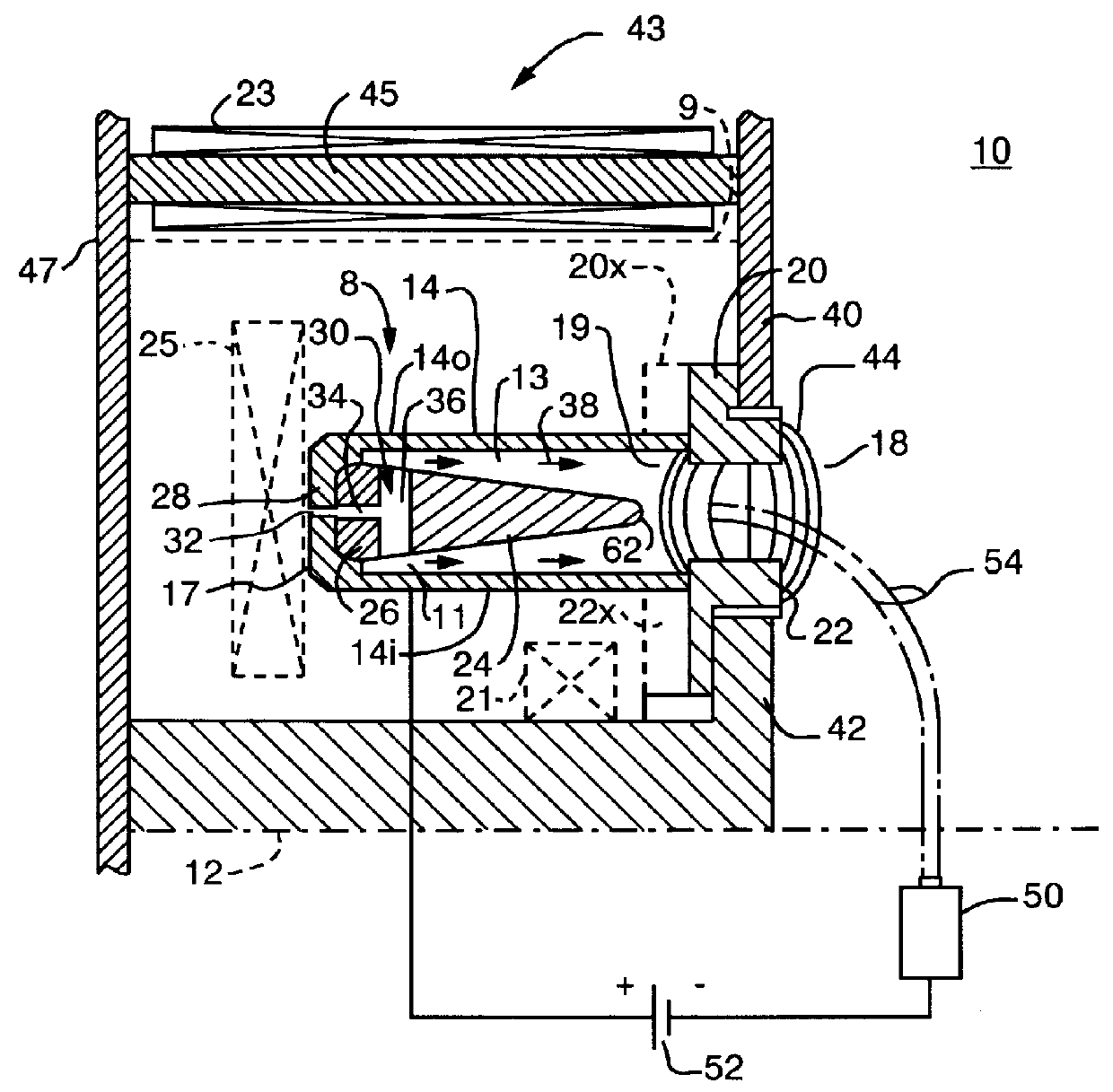
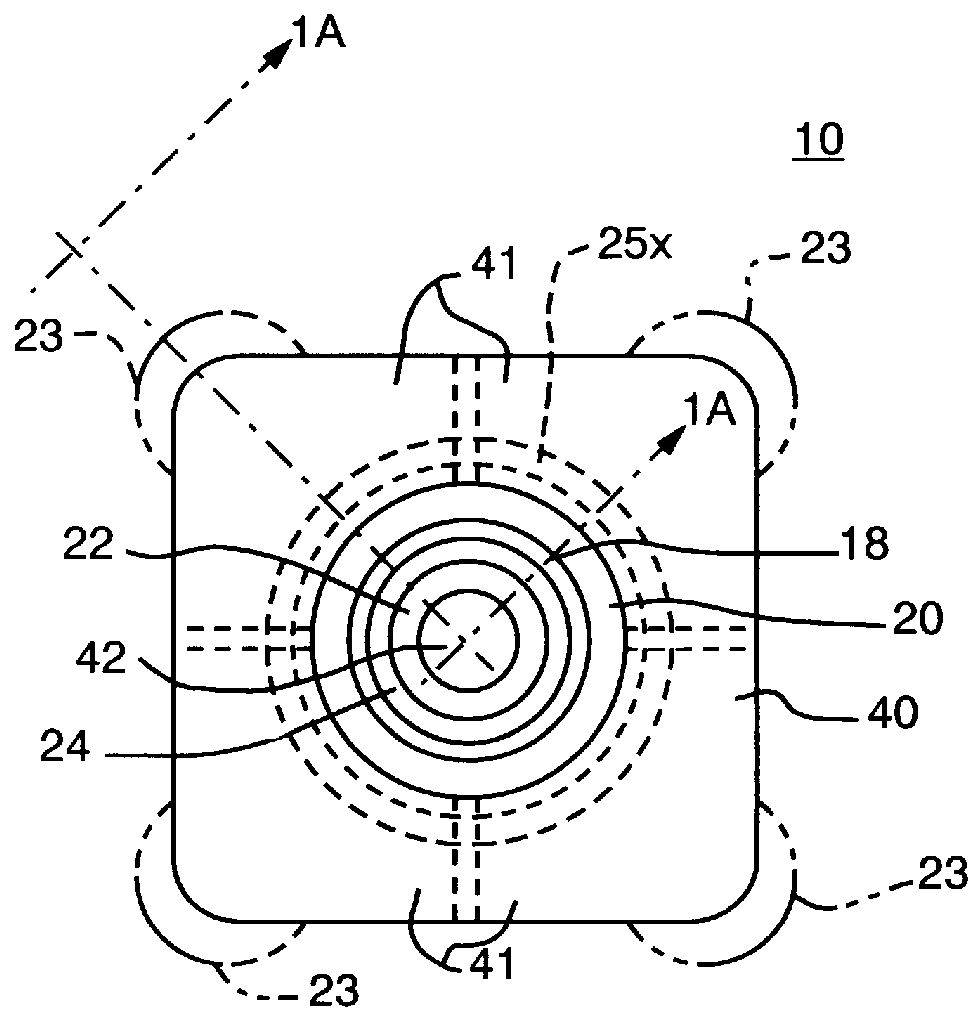
FIG. 1A is a schematic cross-sectional view along lines 1A--1A of FIG. 1B of a portion of a plasma accelerator according to this invention which is circularly symmetrical about its center line;

FIG. 1B is a front diagrammatic view of the plasma accelerator of FIG. 1A;

FIG. 1C is a view similar to FIG. 1B of a non-circular plasma accelerator according to this invention;

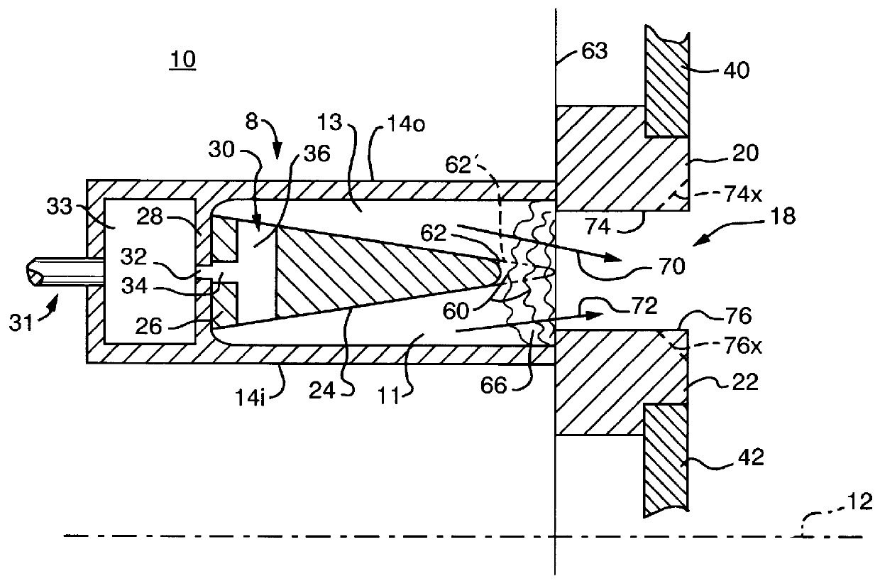
FIG. 2 is a more detailed schematic view of a portion of the device shown in FIG. 1 illustrating the equipotential region and initial ion trajectories resulting therefrom;

FIG. 3 is a view similar to FIG. 2 illustrating the path of secondary emission electrons transverse to the path of the propellant neutrals or atoms;

FIG. 4 is a simplified schematic view showing the various electric potential schemes that can be applied between the inner anode and c...


PUM


Abstract

A Hall field plasma accelerator with closed electron drift includes a composite anode including a housing with inner and outer walls which form an outer anode and an inner anode forming inner and outer distribution zones; the housing is electrically conductive and has an upstream end and an exit port electrically insulated from the housing; the composite anode includes an input distribution system for introducing plasma gas into the distribution zones; poles establish a magnetic field across the exit port and a cathode establishes an electron flow through the magnetic field toward the composite anode and creates an electric field through the exit port; the electrons ionize the plasma gas that is accelerated by the electric field through the exit port.

Description

This invention relates to an improved Hall field plasma accelerator.BACKGROUND OF INVENTIONHall field plasma accelerators (or thrusters) with closed electron drift employ electrons discharged from a separate cathode and directed toward an anode by an applied electric field (E) through an applied magnetic field (B) which is generally orthogonal to the applied electric field and in which the electrons collide with atoms of a gas or propellant to create a plasma which consists of approximately equal number of electrons and ions which are accelerated out of the accelerator / thruster by the applied electric field. Generally the Larmor radius .rho..sub.e of the electrons is much smaller than the characteristic length L of the accelerator so the electrons tend to move in a helical path about the magnetic lines as they move from line to line azimuthally and drift generally toward the anode. The ions in contrast have a Larmor radius .rho..sub.i which is much greater than the characteristic le...

Claims


Application Information

Patent Timeline
IPC IPC(8): F03H1/00
CPCF03H1/0075
Inventor HRUBY, VLADIMIR J.
Owner BUSEK
Why Eureka
Try Eureka