Process for making ammonia from heterogeneous feedstock

Inactive Publication Date: 2000-07-11
RINECO CHEM INDS
View PDF15 Cites 16 Cited by
  • Summary
  • Abstract
  • Description
  • Claims
  • Application Information

AI Technical Summary

Problems solved by technology

However, these conventional processes are not designed to operate with a heterogeneous feedstock.
Another synergy that results as a cons

Method used


Image

  • Process for making ammonia from heterogeneous feedstock

Examples


Embodiment Construction

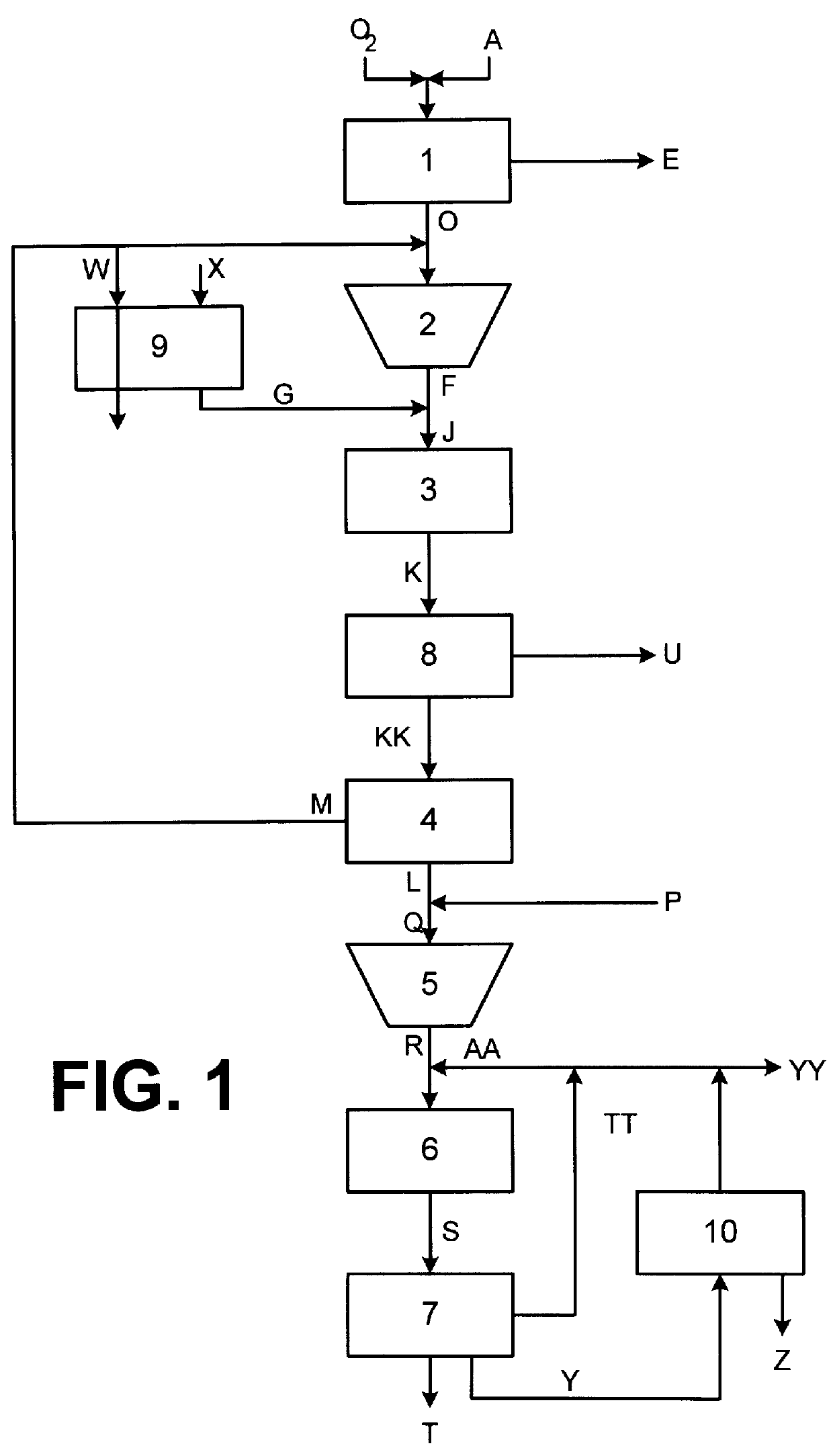
FIG. 1 is a process schematic detailing embodiments of the present invention. A carbon-containing heterogeneous feedstock stream A is fed along with an oxygen stream B to gasifier in the gasifier / gas cleanup unit 1. Solid and liquid carbon-containing waste materials containing large amounts of inorganic material are processible as heterogeneous feedstock A according to the present invention, as long as the net heating value of the heterogeneous feedstock A is greater than about 3,000 Btu / lb. Examples of the carbon-containing waste material that can be processed according to the present invention include oil-contaminated dirt, demolition debris, respirator masks, paint and contaminated rags.

In gasifier / gas cleanup unit 1, carbon in heterogeneous feedstock A is partially oxidized to form a synthesis gas D containing primarily CO. After partial oxidation of carbon in heterogeneous feedstock A, the inorganic residue E is removed from the gasifier / gas cleanup unit 1. The inorganic residu...


PUM


Abstract

Ammonia is made from a carbon-containing heterogeneous feedstock by partially oxidizing the feedstock at low pressure to generate a synthesis gas containing CO; isothermally shift reacting the synthesis gas with steam to form H2; cryogenically removing portions of the CO2 and Ar from the shifted gas; purifying the H2 in a pressure swing adsorber; mixing the purified H2 with high purity N2; and converting the H2 and N2 into ammonia. The tail stream from the pressure swing adsorber can be recycled with the synthesis gas for control purposes and/ or used as boiler fuel. The reduced volume of purge gas purged from the ammonia synthesis loop allows ammonia contained in the purge gas stream to be recovered by cryogenic condensing.

Description

1. Field of InventionThis invention relates to processes for making ammonia. More specifically, this invention relates to processes for manufacturing ammonia on an industrial scale from a heterogeneous feedstock containing a time varying variety of different materials having different carbon contents and including, for example, solid or liquid carbon-containing waste materials.2. Description of Related ArtAmmonia is produced on an industrial scale by the catalytic conversion of nitrogen and hydrogen at high pressures and temperatures. While the nitrogen typically comes from air, the hydrogen is usually produced by reacting carbon-containing feedstocks with steam (steam reforming) or oxygen (partial oxidation). For example, methane or natural gas can be catalytically steam reformed (CH.sub.4 +H.sub.2 O.fwdarw.CO+3H.sub.2). In contrast, coal, coke and naphtha or heavy oils, for example, can undergo reactions including partial oxidation (2C+O.sub.2 .fwdarw.2CO) and water gas reaction (...

Claims


Application Information

Patent Timeline
IPC IPC(8): C01B3/00C01B3/02C01B3/48C01B3/50C01B3/56C01C1/04C01C1/00
CPCC01B3/025C01B3/48C01B3/506C01B3/56C01C1/0458C01C1/0476C01B2203/025C01B2203/0283C01B2203/0425C01B2203/043C01B2203/046C01B2203/0475C01B2203/068C01B2203/0894C01B2203/1041C01B2203/1076C01B2203/1205C01B2203/146C01B2203/147C01B2203/148Y02P20/52
Inventor WHITNEY, JOHN P.RAO, ASHOK D.
Owner RINECO CHEM INDS
Why Eureka
Try Eureka