Method of opening and filling carbon nanotubes

a carbon nanotube and tube technology, applied in the field of carbon nanotubes, can solve the problems of limited tube filling, limited tube filling, and inability to apply techniques to a limited number of materials

Inactive Publication Date: 2000-07-18
ISIS INNOVATION LTD
View PDF7 Cites 126 Cited by
  • Summary
  • Abstract
  • Description
  • Claims
  • Application Information

AI Technical Summary

Problems solved by technology

However, no suitable method for opening and filling the carbon nanotubes with a variety of materials is currently available.
These high temperature methods favour the production of metal carbides, the techniques can only be applied to a limited number of materials.
About it of the tubes were filled in this manner and the presence of internal caps frequently limit the amount of tube filling.
The filling of open tubes prepared by these gas phase oxidations has proved difficult, probably due to the presence of amorphous carbon blocking the tubes.sup.12.

Method used


Image

  • Method of opening and filling carbon nanotubes
  • Method of opening and filling carbon nanotubes
  • Method of opening and filling carbon nanotubes

Examples


example 2

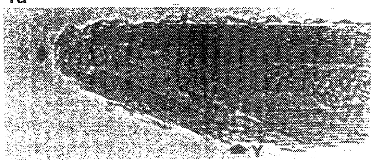
The preparation of filled nanotubes was carried out by suspending capped nanotubes in a solution of nitric acid Containing hydrated nickel nitrate (2.5% w / w) and refluxing for the 4.5 hours. The resulting insoluble black product was filtered and dried in an 100.degree. C. overnight. the sample was then heated in a stream of helium at a rate of 10.degree. C. / min from room temperature to 100.degree. C. and kept at this temperature for an hour before ramping at 4.degree. C. / min to 450.degree. C. The sample was then annealed for 5 hours at this temperature. Electron micrographs showed that many (ca. 80%) of the nanotubes had been opened by nitric acid treatment and that of these about 60-70% contained nickel material. Some nickel-containing material was also observed on the exterior of the nanoparticles and nanotubes. No intercalation of nickel material between carbon layers of the nanotubes was observed. A typical micrograph of a nickel containing tube is shown in FIG. 2. Close examina...

example 3

Tubes filled with reduced nickel oxides, when treated with carbon monoxide and hydrogen mixtures, will catalyse the reduction of the carbon monoxide by the hydrogen giving methane. In other words, the reduced nickel oxide tubes act as methanation catalysts in a typical test run, a mixture of CO and hydrogen (1:1 by volume) was passed over a 50 mg sample of nanotubes containing reduced nickel oxide at a flow rate of 25 cm.sup.3 per minute and at a temperature of 200 to 400.degree. C. Gas chromatograph analysis of the outflowing gas showed greater than 80% conversion to the product methane.

example 4

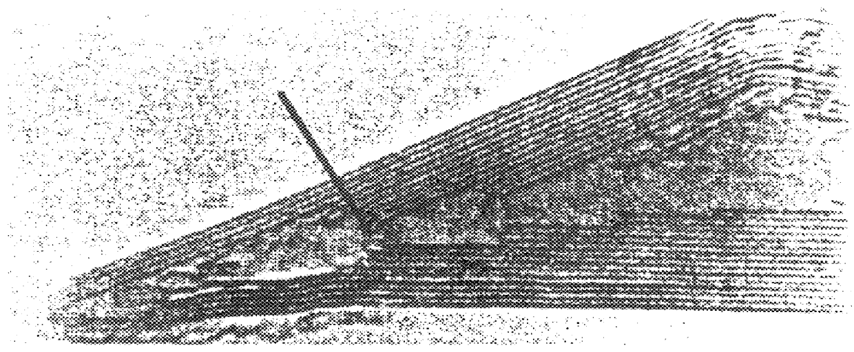
Treatment of closed nanotubes with a nitric acid solution of uranyl nitrate for 4.5 hours gave open-ended nanotubes containing uranium. It is estimated that 70% of the tubes contain uranium oxide material. FIG. 3 shows crystallites in the inner tube with lattice fringes of 3.15.+-.0.005 .ANG.. These are randomly oriented with respect to the graphite layers. The layer separation corresponds to that reported for (111) UO.sub.2+x crystallographic planes. Other interlayer separations determined from the transmission electron microscopy and x-ray powder diffraction spectra are also consistent with the fluorite structure of UO.sub.2+x ; the precise value of x is not known. The UO.sub.2+x crystallites are ellipsoidal with lengths varying between 3-8 nm. The observed contact angles, usually >100.degree. suggest the uranium oxide crystallites wet the carbon surface poorly. We have found that most of the uranium oxide particles can be dissolved from the inner tubes by treatment with concentra...


PUM

PropertyMeasurementUnit
lengthaaaaaaaaaa
lengthaaaaaaaaaa
temperaturesaaaaaaaaaa

Abstract

PCT No. PCT / GB95 / 02235 Sec. 371 Date Apr. 10, 1997 Sec. 102(e) Date Apr. 10, 1997 PCT Filed Sep. 20, 1995 PCT Pub. No. WO96 / 09246 PCT Pub. Date Mar. 28, 1996Method of making carbon nanotubes open on at least one end wherein capped nanotubes are treated with an oxidizing acid such as nitric acid. The treatment is effective to open at least 50% of the nanotubes on at least one end.

Description

Carbon nanotubes, or so called `buckytubes`, were first observed by Iijima in 1991.sup.1. A method for macroscopic synthesis of nanotubes giving gram quantity of the material has been subsequently described.sup.2. Typically, the nanotubes consist of multilayers (normally 2-50) of concentric carbon tubes which are capped at both ends. The tubes are built up of sheets of carbon atoms arranged in hexagons and pentagons, with the pentagons concentrated in areas of low radius of curvature such as the tube ends. The tubes contain a hollow core up to 50 nm across typically 100-200 nm in length.There has been much speculation on the possible physical and chemical properties of filled nanotubes, especially novel magnetic, mechanical, electrical, optical and catalytic properties.sup.3. However, no suitable method for opening and filling the carbon nanotubes with a variety of materials is currently available. There have previously been attempts to insert materials into the tubes by using compo...

Claims


Application Information

Patent Timeline
Patent Type & Authority Patents(United States)
IPC IPC(8): C01B31/00C01B31/02
CPCB82Y30/00B82Y40/00C01B31/0286Y10S423/40Y10S977/848C01B32/178
Inventor GREEN, MALCOLM L. H.TSANG, SHIK C.
Owner ISIS INNOVATION LTD
Why Eureka
Try Eureka