

Method for producing anode material and non-aqueous electrolyte cell employing such materials
a non-aqueous electrolyte and anode technology, which is applied in the direction cell components, electrochemical generators, etc., can solve the problems of increased risk of degradation, increased energy density, and increased cell capacity so as to improve the safety and reliability of non-aqueous electrolyte cells, improve the effect of capacity characteristics and a higher level of energy density
- Summary
- Abstract
- Description
- Claims
- Application Information
AI Technical Summary
Benefits of technology
Problems solved by technology
Method used
Image

Examples
example 5
Preparation of Anode
Ninety parts by weight of artificial graphite obtained by calcining pitch coke at 2,800.degree. C. and 10 parts by weight of PVdF were sufficiently mixed and dispersed in DMF, and the solvent (DMF) was vaporized under reduced pressure. The thus obtained dry product was size-reduced, and was classified to obtain particles 100 .mu.m or less in size. The resulting classified dry product was weighed to obtain a 35-mg weight portion, which was pressure welded on a stainless steel collector 2 cm.sup.2 in area by applying a pressure of 4 t / cm.sup.2. Thus was obtained a pellet-like anode about 0.2 mm in thickness.
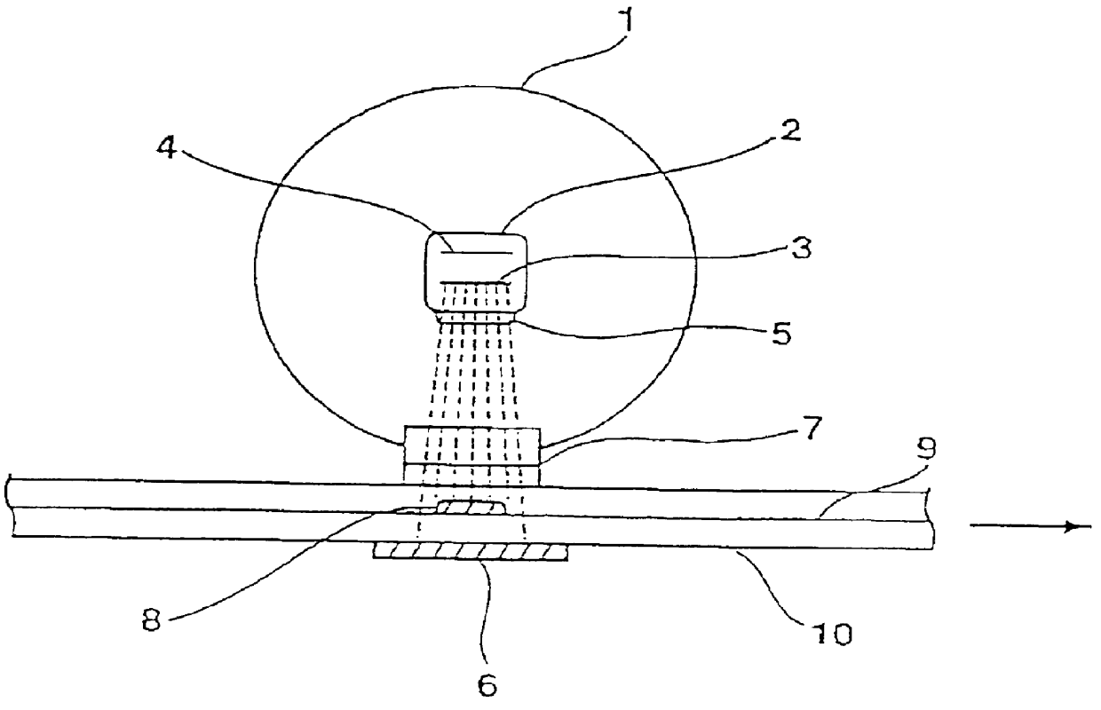
Then, electron beam was irradiated to the both surfaces of the thus obtained pellet-like anode by operating the electron irradiating apparatus (Model CB250 / 15 / 180L manufactured by Iwasaki Electric Co., Ltd.) shown in FIG. 1 under the conditions shown in Table 6.
In case of a carbonaceous material having a specific gravity in a range of from 1.4 to 2.3, the penetr...
example 6
Anodes for Example 6 were prepared by following the same procedure described in Example 5, except for using granular graphite obtained by calcining MCMBs at a temperature of 2,800.degree. C. in the place of granular graphite prepared by calcining pitch coke at 2,800.degree. C. Then, test cells were prepared using the resulting anodes.
Argon-Laser Raman Spectroscopy
Raman spectroscopy was performed on the anode obtained for Example 6 in the same manner as in Example 5. FIG. 10 shows the relation between the ratio in area for the peak at 1350 cm.sup.-1 to that at 1580 cm.sup.-1 and the dose of irradiated electron beam for the anode of Example 6. FIG. 10 reads that, in case of Example 6, the area ratio increases by irradiating electron beam, and that it increases with increasing dose of electron irradiation.
Evaluation
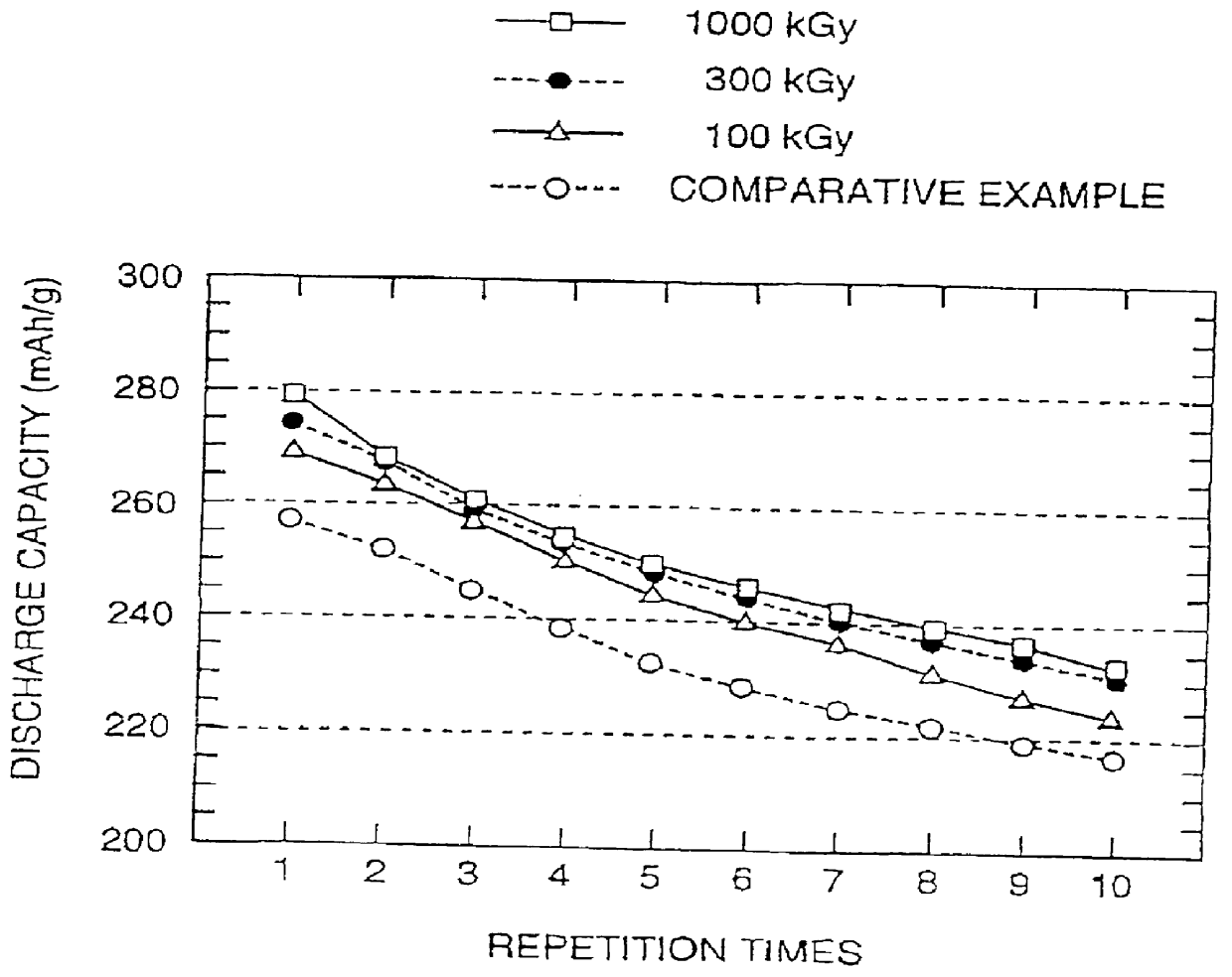
Similar to the case in Example 5, recharging of test cells were performed at a constant current flow of 0.5 mA (i.e., at a current density of 0.27 mA / cm.sup.2) (constant cur...
examples 7 to 9
Anodes for Example 7 were prepared by following the same procedure described in Example 5, except for using non-graphitizable carbon material obtained by calcining phenolic resin at a temperature of 1,100.degree. C. in the place of granular graphite prepared by calcining pitch coke at 2,800.degree. C. Test cells were prepared thereafter by using the resulting anodes.
Anodes for Example 8 were prepared by following the same procedure described in Example 5, except for using non-graphitizable carbon material obtained by calcining furfuryl alcohol resin at a temperature of 1,100.degree. C. in the place of artificial graphite prepared by calcining pitch coke at 2,800.degree. C., and for using a non-aqueous electrolyte obtained by dissolving 1 mol / l of LiPF.sub.6 in a 1:1 by volume mixed solvent of propylene carbonate and dimethyl carbonate. Test cells were prepared thereafter by using the resulting anode.
Anodes for Example 9 were prepared by following the same procedure described for Exa...
PUM
 Abstract
Description
Claims
Application Information