Vehicle positioning method and system thereof

Inactive Publication Date: 2000-12-26
AMERICAN GNC
View PDF3 Cites 212 Cited by
  • Summary
  • Abstract
  • Description
  • Claims
  • Application Information

AI Technical Summary

Benefits of technology

It is a main objective of the present invention to provide an improved fully-coupled vehicle positioning process and system thereof, in which the velocity and acceleration from an inertial navigation processor are used to aid the

Problems solved by technology

Global positioning system GPS contains a number of error sources: the signal propagation errors, satellites errors, and the selective availability.
The user range error (URE) is the resultant ranging error along the line-of-sight between the user and the global positioning system satellite.
Global positioning system errors tend to be relatively constant (on average) over time, thus giving global positioning system long-term error stability.
However, the signals of the global positioning system may be intentionally or unintentionally jammed or spoofed, or the global positioning system (GPS) receiver antenna may be obscured during vehicle attitude maneuvering, and the global positioning system signals may be lost when the signal-to-noise ratio is low and the vehicle is undergoing highly dynamic maneuvers.
However, with the availability of newer gyros and accelerometers, strapdown inertial navigation systems become the predominant mechanization due to their low cost and reliability.
However, an inertial navigation system is expensive and subject to drift over an extended period of time.
It means that the position error increases with time.
This error propagation characteristic is primarily caused by its inertial sensor error sources, such as gyro drift, accelerometer bias, and scale factor errors.
The inherent drawbacks of a stand-alone inertial navigation system (INS) and a stand-alone global positioning system (GPS) show that a stand-alone inertial navigation system or a stand-alone global positioning system can not meet mission requirements under some constra

Method used


Image

  • Vehicle positioning method and system thereof
  • Vehicle positioning method and system thereof
  • Vehicle positioning method and system thereof

Examples


Embodiment Construction

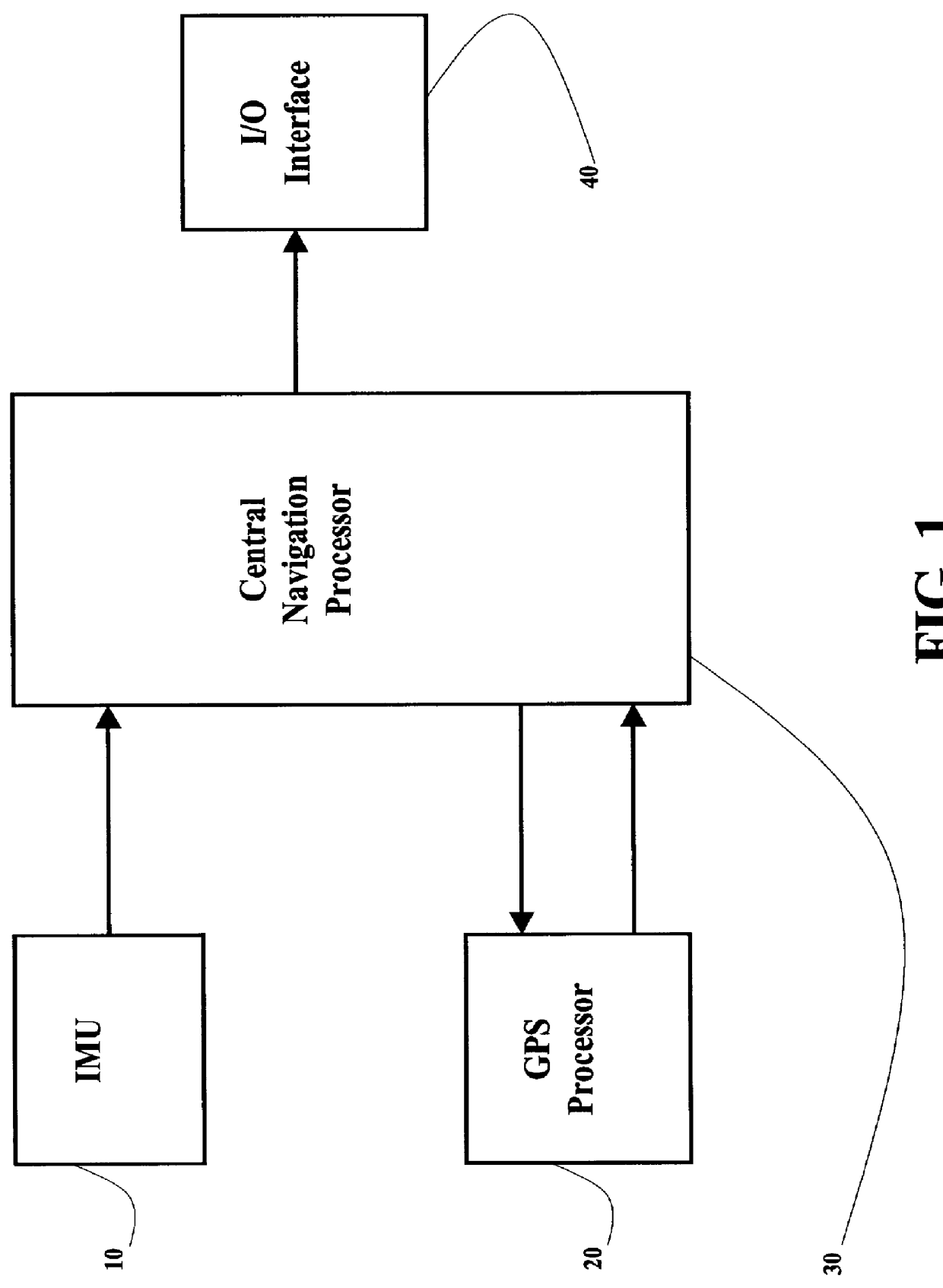
The improved fully-coupled GPS / IMU vehicle positioning system of the present invention, as shown in FIG. 1, comprises an IMU (inertial measurement unit) 10 and a GPS (global positioning system) processor 20 which are connected to a central navigation processor 30. The navigation solution is output to an I / O (input / output) interface 40.

The improved fully-coupled global positioning system / inertial measurement unit (GPS / IMU) vehicle positioning process of the present invention comprises the following steps.

a) Receive GPS measurements, including pseudorange, carrier phase, and Doppler shift, from the GPS processor 20 and pass them to the central navigation processor 30. Receive inertial measurements, including body angular rates and specific forces, from the IMU 10 and inject them into an INS processor 31 (as shown in FIG. 4) of the central navigation processor 30.

b) Blend the output of the INS (inertial navigation system) processor 31 and the GPS measurements in a Kalman filter 33 (as ...


PUM


Abstract

An improved fully-coupled vehicle positioning process and system thereof can substantially solve the problems encountered in global positioning system-only and inertial navigation system-only, such as loss of global positioning satellite signal, sensibility to jamming and spoofing, and inertial solution's drift over time, in which the velocity and acceleration from an inertial navigation processor are used to aid the code and carrier phase tracking of the global positioning system satellite signals, so as to enhance the performance of the global positioning and inertial integration system, even in heavy jamming and high dynamic environments. The improved fully-coupled GPS/IMU vehicle positioning system includes an IMU (inertial measurement unit) and a GPS processor which are connected to a central navigation processor to produce navigation solution that is output to an I/O (input/output) interface.

Description

FIELD OF THE PRESENT INVENTIONThe present invention relates generally to a global positioning system and inertial measurement unit (GPS / IMU) integrated positioning and navigation method, and more particularly to an improved fully-coupled integration method of the global positioning system (GPS) receiver and the inertial measurement unit (IMU), which allows the mutual aiding operation of the global positioning system (GPS) receiver and the inertial navigation system (INS) at an advanced level with features of inertial aiding global positioning system satellite signal tracking and rapid global positioning system signal carrier phase integer ambiguity resolution.BACKGROUND OF THE PRESENT INVENTIONThe global positioning system user equipment, which consists of an antenna, a signal processing unit, and associated electronics and displays, receives the signals from the global positioning system satellites to obtain position, velocity, and time solution. The global positioning system princ...

Claims


Application Information

Patent Timeline
IPC IPC(8): G01C21/10G01C21/16G01S5/14G01S19/44G01S19/49G01S19/55
CPCG01C21/165G01S19/44G01S19/26G01S19/215
Inventor LIN, CHING-FANG
Owner AMERICAN GNC
Why Eureka
Try Eureka