Method of forming electronically conducting polymers on conducting and nonconducting substrates

a technology of electronic conductivity and polymerization method, which is applied in the direction of magnetic/electric field screening, metallic pattern materials, hydrocarbons, etc., can solve the problems of increasing stringent requirements for all production steps, difficult removal from waste streams, and reducing the efficiency of electroless copper waste treatment,

Inactive Publication Date: 2001-04-03
LYNNTECH
View PDF29 Cites 48 Cited by
  • Summary
  • Abstract
  • Description
  • Claims
  • Application Information

AI Technical Summary

Problems solved by technology
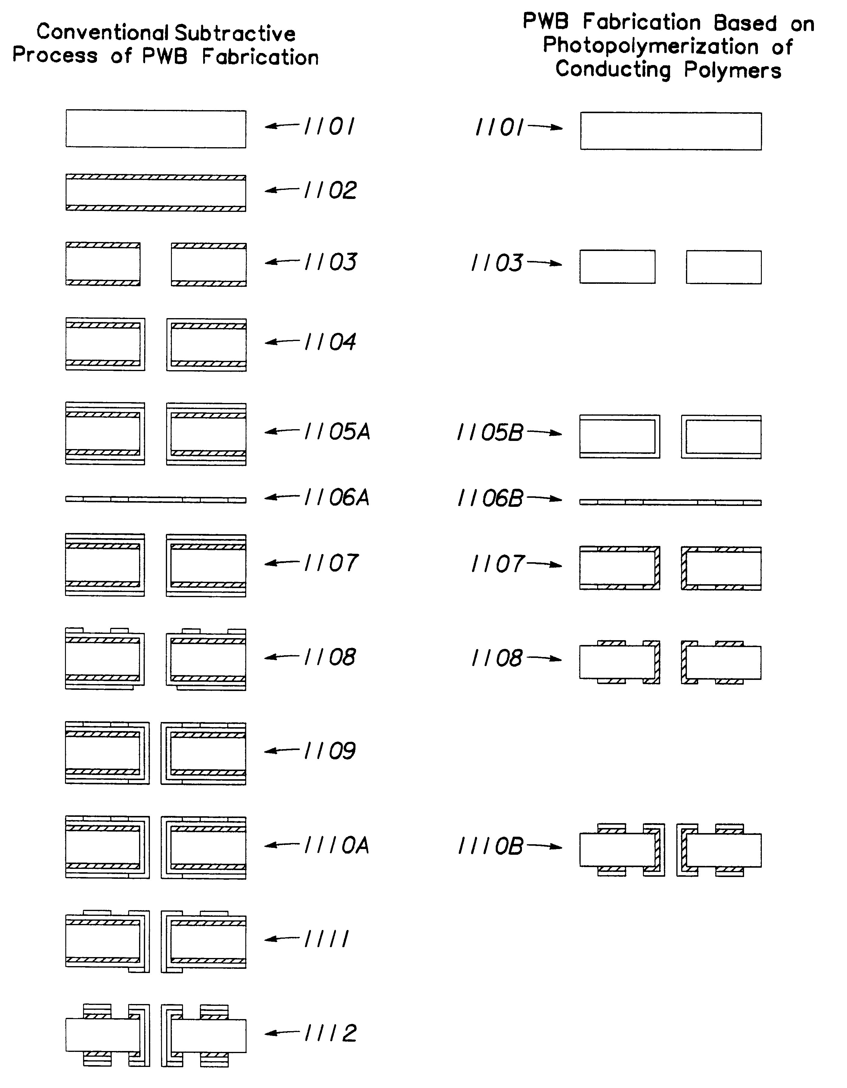
Current demand for increasingly complex PWBs has resulted in increasingly stringent requirements for all production steps.
However, electroless deposition of copper requires a potent reducing agent, such as formaldehyde--a reported carcinogen.
Most electroless copper solutions contain cyanide and chelating agents, which are difficult to remove from waste streams.
Besides the normal drag-out associated with wet processing, "bail-out" (required to maintain solution balance and periodic bath changes) renders waste treatment of electroless copper far more expensive than electroplated copper.
Despite numerous attempts over the last 10 years, conversion to a direct metallization process has not gained widespread acceptance, and only about five percent of PWB manufacturers worldwide have eliminated metallization by electroless copper.
This obviously creates a roadblock for achieving a free-flowing process.
Electronics manufacturers have not realized or appreciated the benefits that direct metallization can provide.
The lack of processability of conducting polymer materials, e.g., solution or melt processing, infusability and poor mechanical properties, e.g., ductility, have slowed down their emerging commercial applications.
While electrochemical preparation of conducting polymers has been shown to be the most satisfactory process from the viewpoint of fundamental investigations, it is likely to be inappropriate for the large-scale industrial production of bulk quantities of these materials.
The presence of plated-through-holes (PTHs 0.062-0.04 in) and vias (<0.10 in) in ever-increasing numbers, will present a challenge in laminating, drilling and metallization.
Therefore, cations having too high an oxidation potential are not suitable for photopolymerization of polypyrrole.
Several attempts were made to use organic electron acceptors, but photopolymerization of black conductive PPY films was unsuccessful.
In general, both electropolymerized and photopolymerized polypyrrole films suffer from poor mechanical properties.
They lack flexibility, either as stand alone films or as coatings.

Method used


Image

  • Method of forming electronically conducting polymers on conducting and nonconducting substrates
  • Method of forming electronically conducting polymers on conducting and nonconducting substrates
  • Method of forming electronically conducting polymers on conducting and nonconducting substrates

Examples


example 2

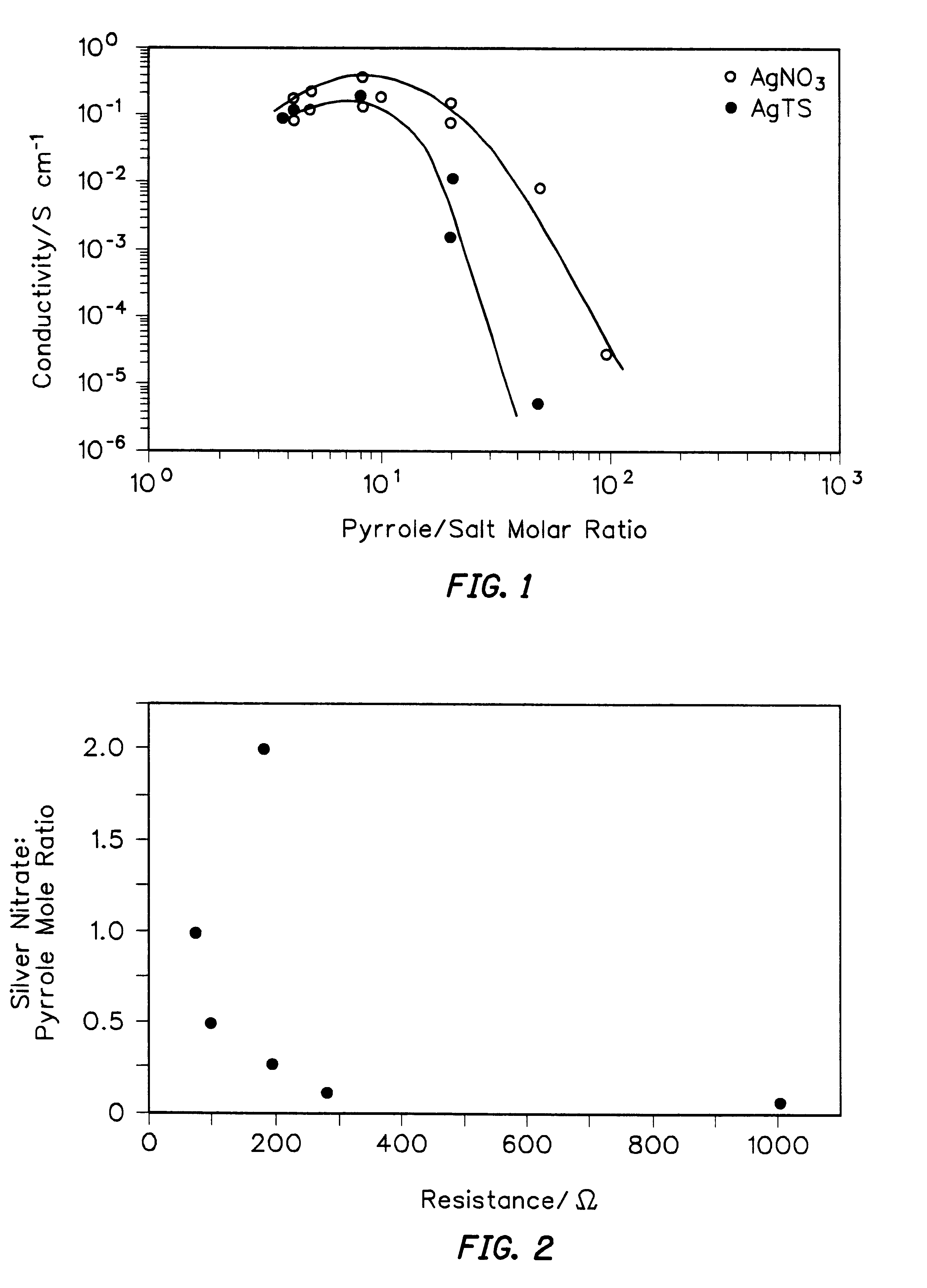
In order to improve the mechanical properties of PPY films three different electron acceptor salts were investigated: AgNO.sub.3, AgTs and AgBF.sub.4. It has been reported that incorporation of tosylate anions improves the mechanical properties of electrochemically formed PPY films. Thus, these three electron acceptor salts were added to photopolymerizable formulations using pyrrole: acceptor molar ratios ranging from 100:1 to 4:1, the latter being closest to the ratio of pyrrole monomer to positive charge found in electrochemically polymerized films. FIG. 1 shows the dependence of electrical conductivity on the concentration of electron acceptors (AgNO.sub.3 and AgTs) added to the formulations. Both curves exhibit a maximum conductivity value of approximately 0.1-0.3 S cm.sup.-1 at pyrrole:salt molar ratios between about 3:1 and about 8:1. A steep decrease in conductivity occurred at molar ratios higher than 15:1. In the case of AgTs, at low added salt concentrations, the conductiv...

example 3

A series of experiments were performed to examine the electrical resistance of photopolymerized polypyrrole films as a function of monomer / electron acceptor mole ratio in the starting formulation. A mole ratio range of 20:1 to 0.5:1 (pyrrole:silver nitrate) was investigated. The solutions were prepared in one ml of pyrrole monomer and varying amounts of silver nitrate. Pyrrole films of constant thickness (ca. 60 microns) were produced. A minimum in resistance (Van der Pauw method) of ca. 80 .OMEGA. was observed at a 1:1 mole ratio of monomer to silver nitrate. Results shown in FIG. 2 demonstrate that by simple adjustment of the concentration of starting formulation components (monomer and electron acceptor) an order of magnitude change in resistance could be obtained.

example 4

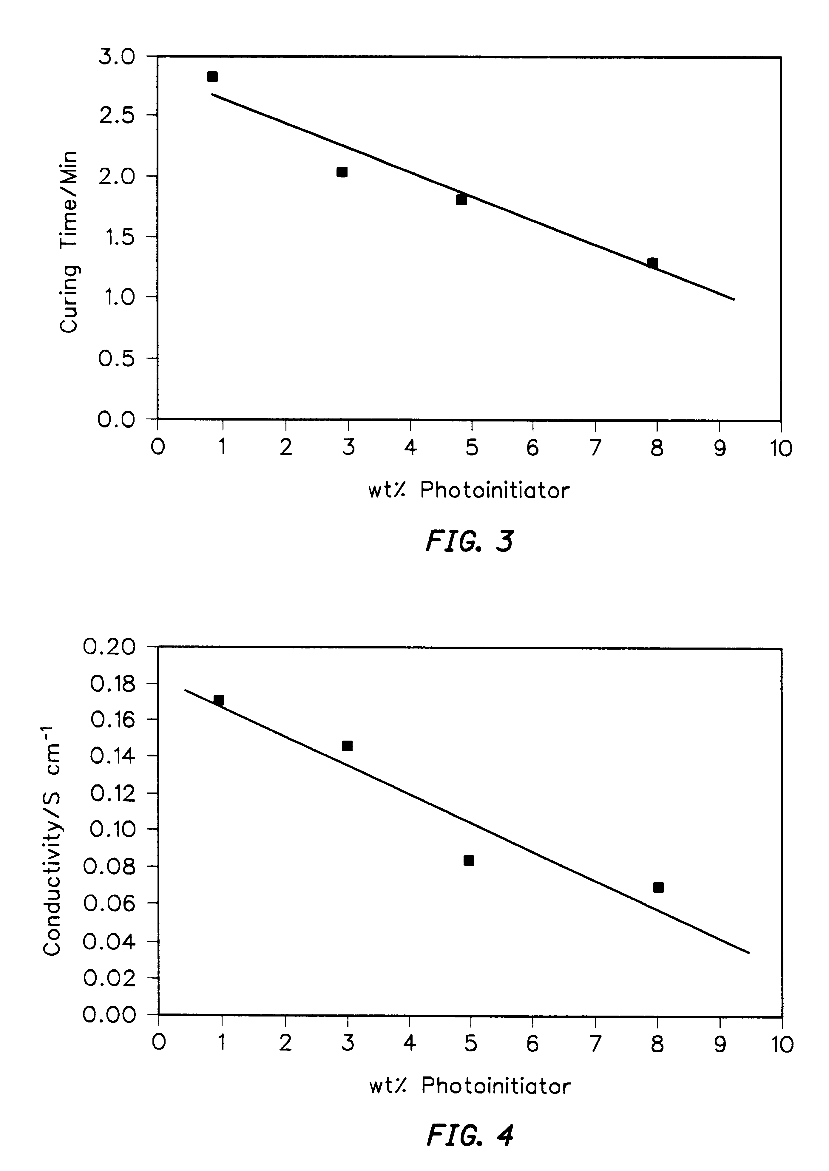
Simple tests of thick film curing were performed by simultaneous illumination of formulations containing photoinitiators added at 3 wt % to an 8:1, pyrrole:AgNO.sub.3 solution. Exposure to UV light was brought about from the top of miniature glass vials (0.7 cm dia. and 1.1 cm height) containing different photoinitiators. The process of photopolymerization was closely followed under low illumination conditions (corresponding to a temperature of 30-32.degree. C.), in order to determine the changes taking place during photopolymerization. In all four vials the polymerization process went through different stages which affected the color of the bulk and / or surface layers of the formulations and the speed of solidification. From this simple experiment it was observed that cationic photoinitiators exhibited faster curing rates than radical photoinitiators. Especially, Irgacure 261 demonstrated better curing (in line with weak absorption of 366 nm light), as evidenced by a deeper and more...


PUM

PropertyMeasurementUnit
weight percentaaaaaaaaaa
molar ratioaaaaaaaaaa

Abstract

The present invention provides electronically conducting polymer films formed from photosensitive formulations of pyrrole and an electron acceptor that have been selectively exposed to UV light, laser light, or electron beams. The formulations may include photoinitiators, flexibilizers, solvents and the like. These solutions can be used in applications including printed circuit boards and through-hole plating and enable direct metallization processes on non-conducting substrates. After forming the conductive polymer patterns, a printed wiring board can be formed by sensitizing the polymer with palladium and electrolytically depositing copper.

Description

The present invention relates to conductive polymers and their use in electronic applications.More particularly, the present invention relates to the preparation of polypyrrole and its use in preparing electronically conducting polymers on conducting and nonconducting substrates, such as printed circuit boards. Even more particularly, the present invention relates to photosensitive solutions of pyrrole and direct metallization processes for preparing electronic circuits on non-conducting substrates.BACKGROUND OF THE DISCLOSUREThe trend toward miniaturization, integration and automated assembly in the electronics industry is forcing designers to continually increase the component density in integrated circuit manufacturing, interconnection and packaging. Current demand for increasingly complex PWBs has resulted in increasingly stringent requirements for all production steps. To produce high-quality boards at competitive prices means keeping production costs down. This in turn means l...

Claims


Application Information

Patent Timeline
Patent Type & Authority Patents(United States)
IPC IPC(8): C08G61/00C08G61/12C25D5/54C23C26/00G03F7/027H01C7/00H01B1/12H01C17/22H01G9/02H01C17/242H05K3/18H05K9/00H05K1/16H05K1/09H05K3/10C08F2/50H01G9/025
CPCC08G61/124C23C26/00C25D5/54G03F7/027H01B1/12H01C7/005H01C17/242H01G9/025H05K1/095H05K1/16H05K1/167H05K3/185H05K3/188H05K9/0081H05K1/162H05K1/165H05K3/105H05K2201/0329H05K2203/0514C25D5/56
Inventor MURPHY, OLIVER J.HITCHENS, G. DUNCANHODKO, DALIBORCLARKE, ERIC T.MILLER, DAVID L.PARKER, DONALD L.
Owner LYNNTECH
Why Eureka
Try Eureka