Method and apparatus for using an array of grating light valves to produce multicolor optical images

a technology of optical images and arrays, applied in electrical devices, instruments, and piezoelectric/electrostrictive/magnetostrictive devices, etc., can solve the problems of limited liquid crystal lifetime and operating temperature range, limited bandwidth to tens of kilohertz, and inability to meet all the above requirements. achieve the effect of increasing operational speed, and reducing the size of the slm

Inactive Publication Date: 2001-04-17
THE BOARD OF TRUSTEES OF THE LELAND STANFORD JUNIOR UNIV
View PDF5 Cites 154 Cited by
  • Summary
  • Abstract
  • Description
  • Claims
  • Application Information

AI Technical Summary

Benefits of technology

Direct integration with electronics provides an important advantage over non-silicon based technologies like liquid crystal oil-film light valves and electro-optic SLMs, because the device can be made smaller and with greater accuracy. Moreover, the device demonstrates simplicity of fabrication and can be manufactured with only a few lithographic steps.
A further advantage of the present invention is that since the grating light valves utilize diffraction rather than deflection of the light beam as the modulating mechanism, the required mechanical motions are reduced from several microns (as in deformable mirror devices) to tenths of a micron, thus allowing for a potential three orders of magnitude increase in operational speed over other SLM technology. This speed is comparable to the fastest liquid crystal modulators, but without the same complexity in the manufacturing process.
A still further advantage of the present invention is that it provides a miniature means for converting video data to an optical image that can be viewed directly, or can be projected onto a screen or film, or the data can be coupled into a fiberoptic cable for optical transmission to a remote location.

Problems solved by technology

To date, no one SLM design can satisfy all the above requirements.
As a result, different types of SLMs have been developed for different applications, often resulting in trade-offs.
The mechanical motions needed for the operation of the DMD result in bandwidths limited to tens of kilohertz.
However, these devices suffer from the drawbacks of limited liquid crystal lifetimes and operating temperature ranges.
In addition, the manufacturing process is complicated by alignment problems and film thickness uniformity issues.
Although these devices, in addition to achieving fast switching speeds, can achieve large contrast ratios, they suffer from a low (<10%) throughput efficiency and are, therefore, often unsuitable for many applications.
Modulators based on the electro-optic, Franz-Keldysh, Quantum-Confined-Stark or Wannier-Stark effect in III-V semiconductors have high contrast and low insertion loss, but are expensive and not compatible with silicon devices.
Waveguide modulators employing glass or epi-layers on silicon, require too much area and too complex fabrication to be easily integratable with other silicon devices.
Silicon modulators that do not employ waveguides and that are based on the plasma effect, require high electrical drive power and do not achieve high contrast.

Method used


Image

  • Method and apparatus for using an array of grating light valves to produce multicolor optical images
  • Method and apparatus for using an array of grating light valves to produce multicolor optical images
  • Method and apparatus for using an array of grating light valves to produce multicolor optical images

Examples


first embodiment

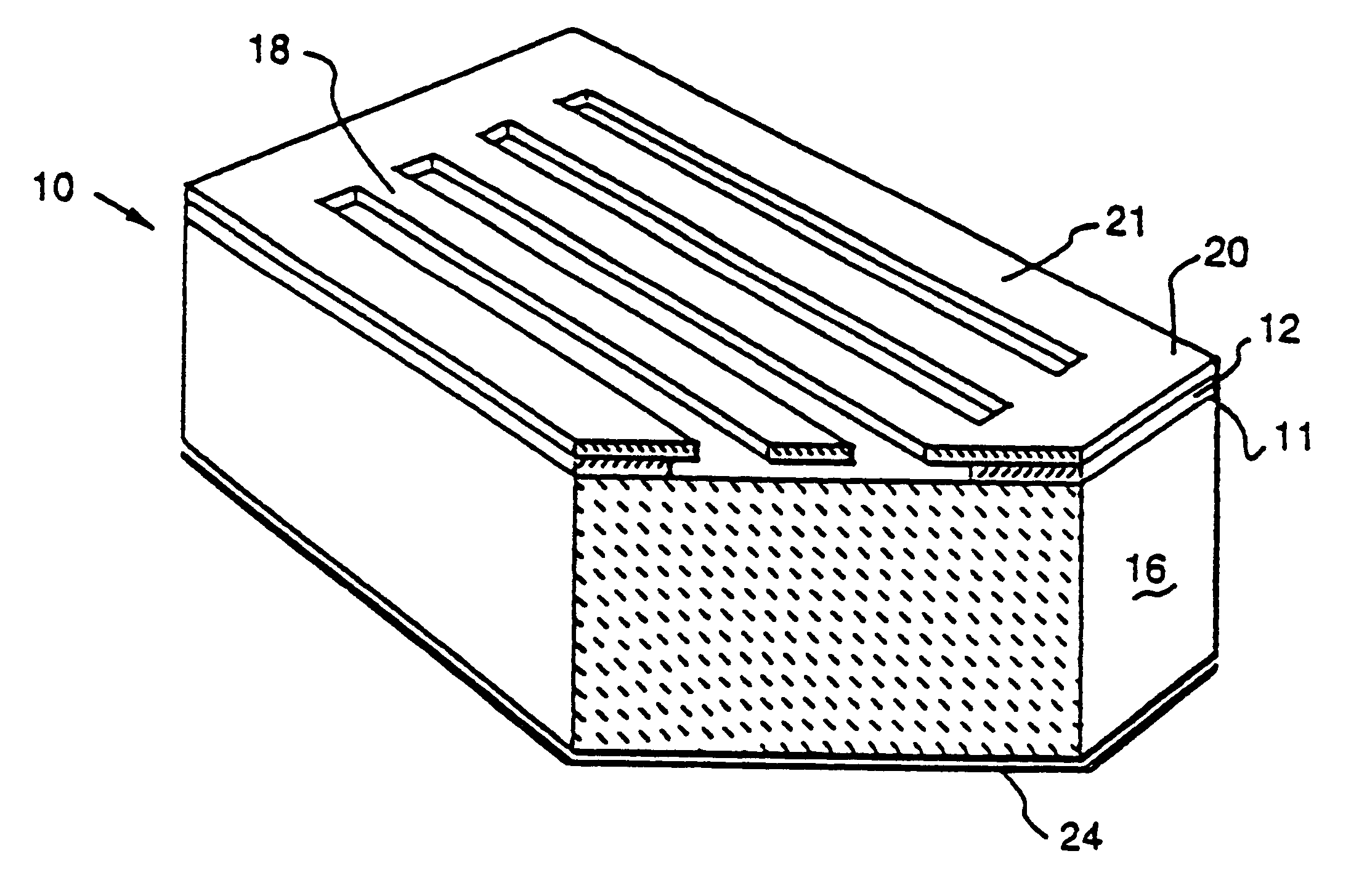
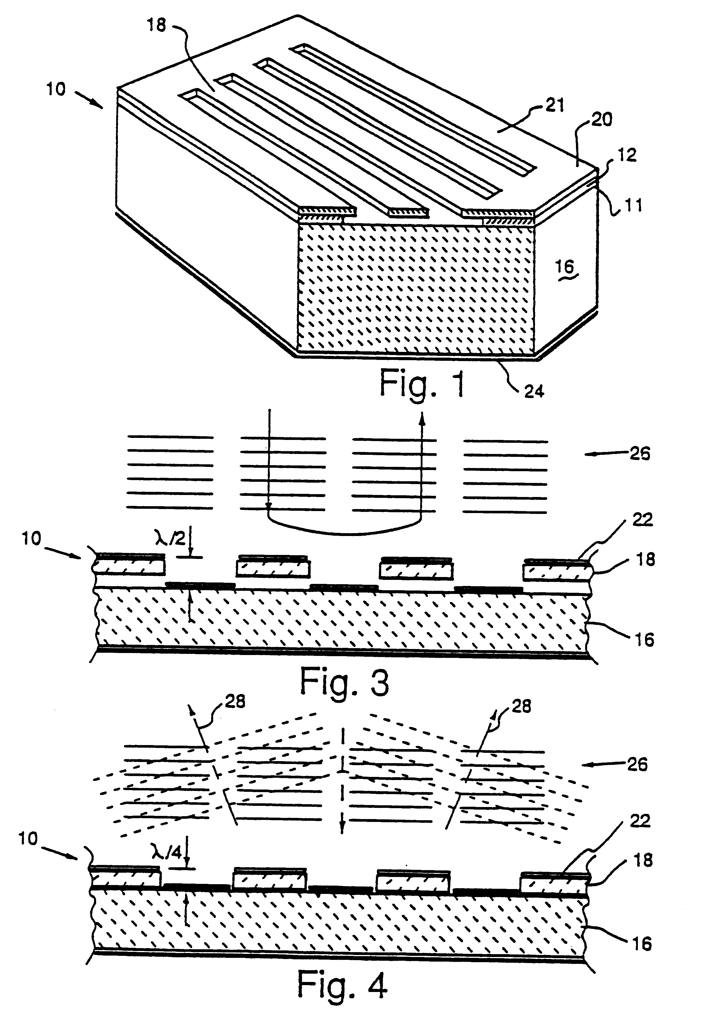
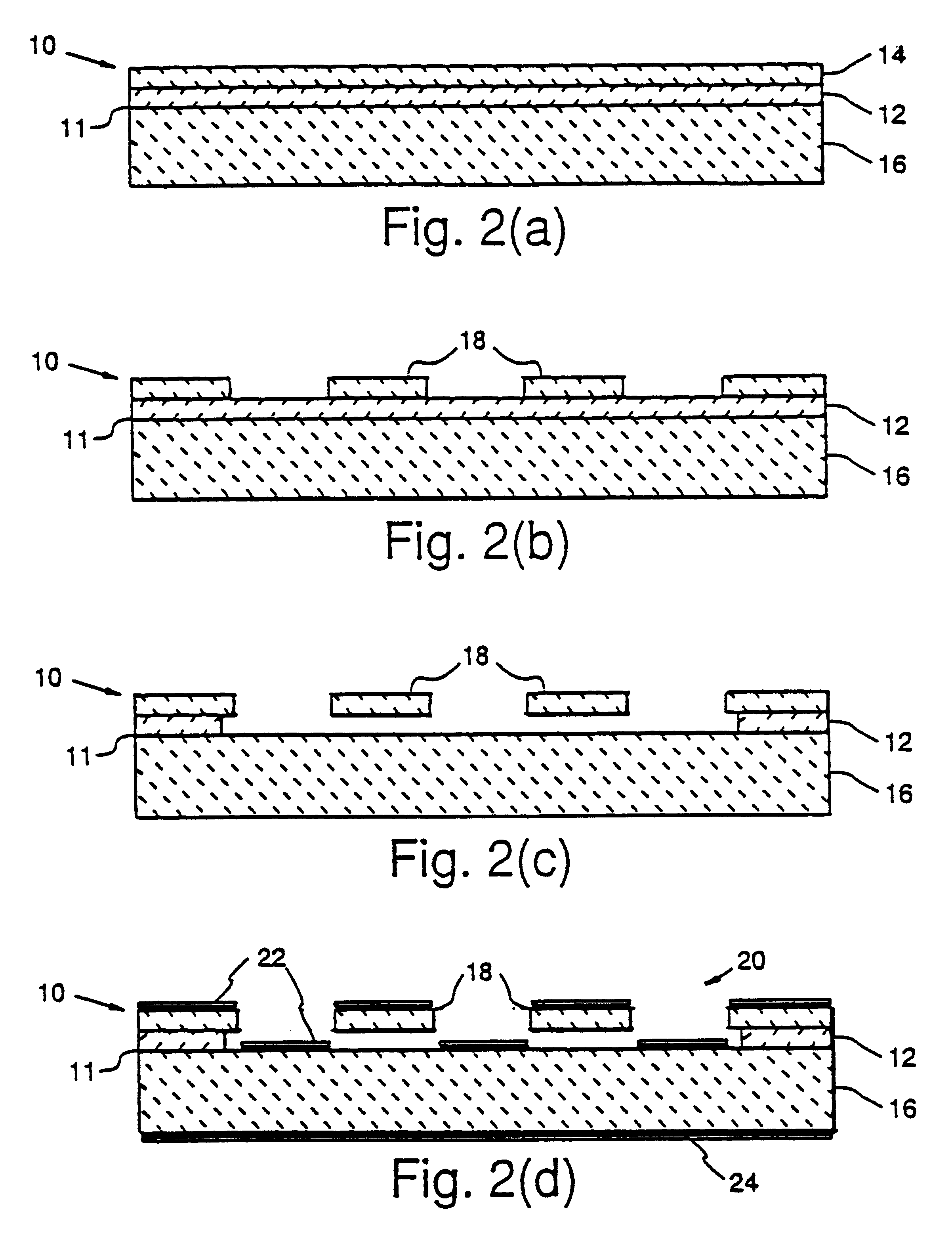
The grating light valve (GLV) or modulator is generally indicated at 10 in FIG. 1. The modulator 10 includes a number of elongated beam-like elements 18 which define a grating that, as will be later explained, can be used to spatially modulate an incident light beam. The elements 18 are formed integrally with an encompassing frame 21 which provides a relatively rigid supporting structure and maintains the tensile stress within the elongated elements 18. This structure defines a grating 20 which is supported by a partially etched silicon dioxide film 12 at a predetermined distance of 213 nm above the surface of a silicon substrate 16.

Before commencing the description of how the modulator 10 is fabricated, it should be noted that, in this case, each of the elements 18 are 213 nm thick and are suspended a distance of 213 nm clear of the substrate 16. This means that the distance from the top of each element to the top of the substrate is 426 nm. This distance is known as the grating am...


PUM


Abstract

A multicolor optical image-generating device comprised of an array of grating light valves (GLVs) organized to form light-modulating pixel units for spatially modulating incident rays of light. The pixel units are comprised of three subpixel components each including a plurality of elongated, equally spaced apart reflective grating elements arranged parallel to each other with their light-reflective surfaces also parallel to each other. Each subpixel component includes means for supporting the grating elements in relation to one another, and means for moving alternate elements relative to the other elements and between a first configuration wherein the component acts to reflect incident rays of light as a plane mirror, and a second configuration wherein the component diffracts the incident rays of light as they are reflected from the grating elements. The three subpixel components of each pixel unit are designed such that when red, green and blue light sources are trained on the array, colored light diffracted by particular subpixel components operating in the second configuration will be directed through a viewing aperture, and light simply reflected from particular subpixel components operating in the first configuration will not be directed through the viewing aperture.

Description

1. Field of the InventionThis invention relates generally to display apparatus for producing optical images, and more particularly to a method and apparatus using an array of sets of grating light valves and a plurality of colored light sources to provide a multicolor image that can be directly viewed or projected onto a screen.2. Brief Description of the Prior ArtDevices which modulate a light beam, e.g. by altering the amplitude, frequency or phase of the light, find a number of applications. An example of such a device is a spatial light modulator (SLM) which is an electronically or optically controlled device that consists of one or two-dimensional reconfigurable patterns of pixel elements, each of which can individually modulate the amplitude, phase or polarization of an optical wavefront.These devices have been extensively developed, particularly for applications in the areas of optical processing and computing. They can perform a variety of functions such as: analog multiplic...

Claims


Application Information

Patent Timeline
Patent Type & Authority Patents(United States)
IPC IPC(8): B81B3/00G02B26/08G02B5/18
CPCG02B5/1828G02B26/0808B81B3/001B81C2201/115
Inventor BLOOM, DAVID M.HUIBERS, ANDREW
Owner THE BOARD OF TRUSTEES OF THE LELAND STANFORD JUNIOR UNIV
Why Eureka
Try Eureka