Multiple stream high pressure mixer/reactor

a mixer/reactor, multi-stream technology, applied in the direction of magnesium compounds, metal/metal-oxide/metal-hydroxide catalysts, silicates, etc., can solve the problems of low efficiency, low efficiency, and low efficiency of output products, so as to achieve less than optimal properties, less than optimal performance, and high intensity

Inactive Publication Date: 2001-04-24
MICROFLUIDICS INT
View PDF3 Cites 178 Cited by
  • Summary
  • Abstract
  • Description
  • Claims
  • Application Information

AI Technical Summary

Benefits of technology

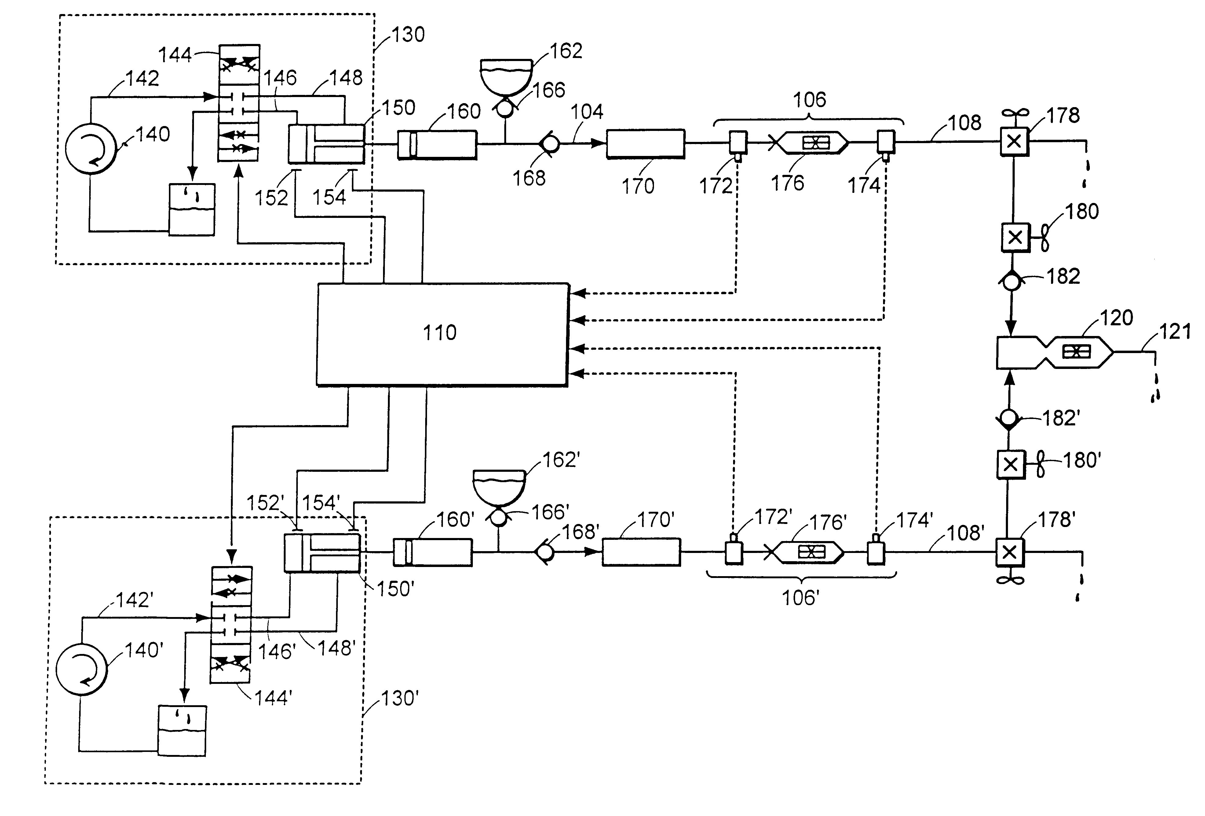
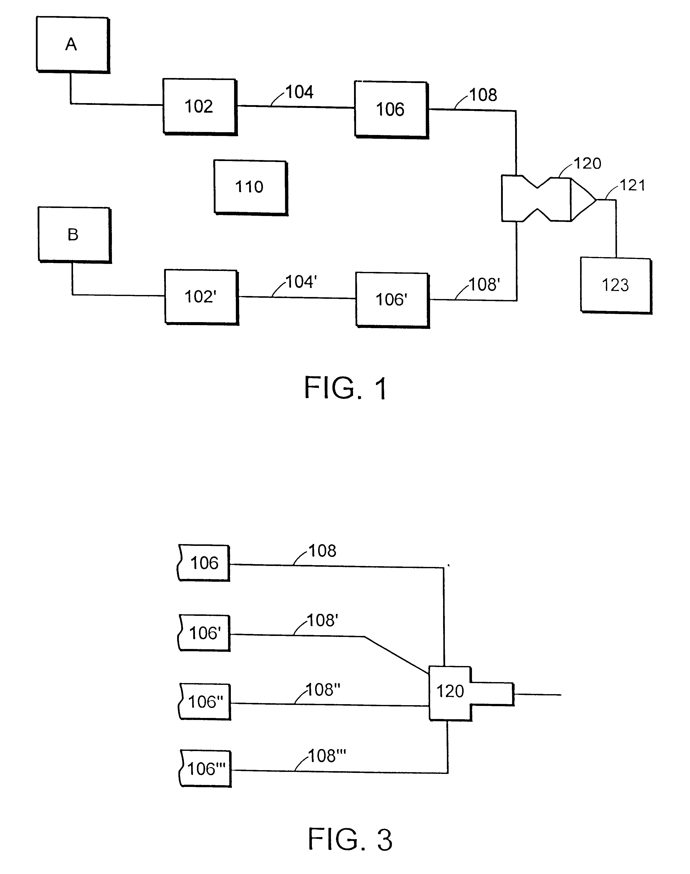
The high pressure pumps 102 and 102' may be any type, including turbine, gear, piston or plunger pumps, and may have single or multiple rotors, pistons, or plungers. For controllability, reliability, and to permit a wider pressure / flow dynamic range, pneumatic or hydraulic pump driving means are preferred over direct or gear driven electric motor drives. Piston and plunger pumps having simple geometries can be assembled from simple components which leads to better reliability through fewer and less complicated parts and also to more gentle and predictable handling of a source material. Thus piston or plunger pumps are currently preferred over turbines and other rotating pumps.
In addition to the homogeneity of the precipitated product, another property of the product which can be important is the crystallite size. Smaller crystallite sizes lead to materials which have a higher surface area, which is important for many applications in catalysis and adsorption. The crystallite size of the product can be controlled in part by the mixing parameters employed during the precipitation. For a given mass of reacting species, the crystallite size is determined by the number of nuclei that are formed upon mixing, which then undergo crystal growth to the final product. In some cases, the nucleation is controlled by the amount of impurities in solution, and is driven by so-called heterogeneous nucleation. However, in other cases the process is driven by homogeneous nucleation, which occurs when the local concentration exceeds supersaturation. As the quality of the mixing of the solutions improves, the degree of supersaturation of the solutions throughout the reactor vessel can be increased. As a result, a larger quantity of nuclei can be formed, resulting in a greater quantity of crystallites being produced for the same overall weight of product. A second aspect of this invention is therefore to provide a means to produce a precipitated product having a small crystallite size, based on the application of intense mixing during precipitation.

Problems solved by technology

If multiple streams of chemical reactants are combined with less than optimum mixing, less than acceptable output product compositions may result.
Examples of such compromised output products include non-uniform seed precipitation products, incompletely reacted source materials, isolation of unreacted source material by reacted product, liquid striation, and the like.
However, a stirred tank reactor has several limitations, especially when used to perform fast chemical reactions.
The flow field is inhomogeneous and generally of low intensity and the predominant flow pattern is back-mixing, making scale-up difficult due to the complexity of the flow.
This often leads to large scaling ratios, i.e. due to inefficiencies in mixing more source materials are required to obtain a desired output quantity.
It is also known that mixing can dramatically affect the properties of the final product of a chemical reaction, particularly a precipitation reaction.
However, at the reactant stream pressures used in the present invention, i.e. about 8,000 psi and above, control valves and materials are not available to provide the required degree of flow control for the low viscosity fluids used herein.
While gear pumps have been used to extrude high viscosity thermoplastic materials at pressures up to 30,000 psi, they are not useful with the low viscosity source material streams of the present invention.
The low viscosity streams would push past the gear-to-housing seals and the gear pumps could not provide adequate flow regulation.
Moreover, even making flow measurements at pressures above 5,000 psi exceeds the capability of many conventional fluid flow techniques.

Method used


Image

  • Multiple stream high pressure mixer/reactor
  • Multiple stream high pressure mixer/reactor
  • Multiple stream high pressure mixer/reactor

Examples


example 2

Preparation of an Aluminosilicate Gel Using the Dual Stream Mixer / Reactor of the Invention

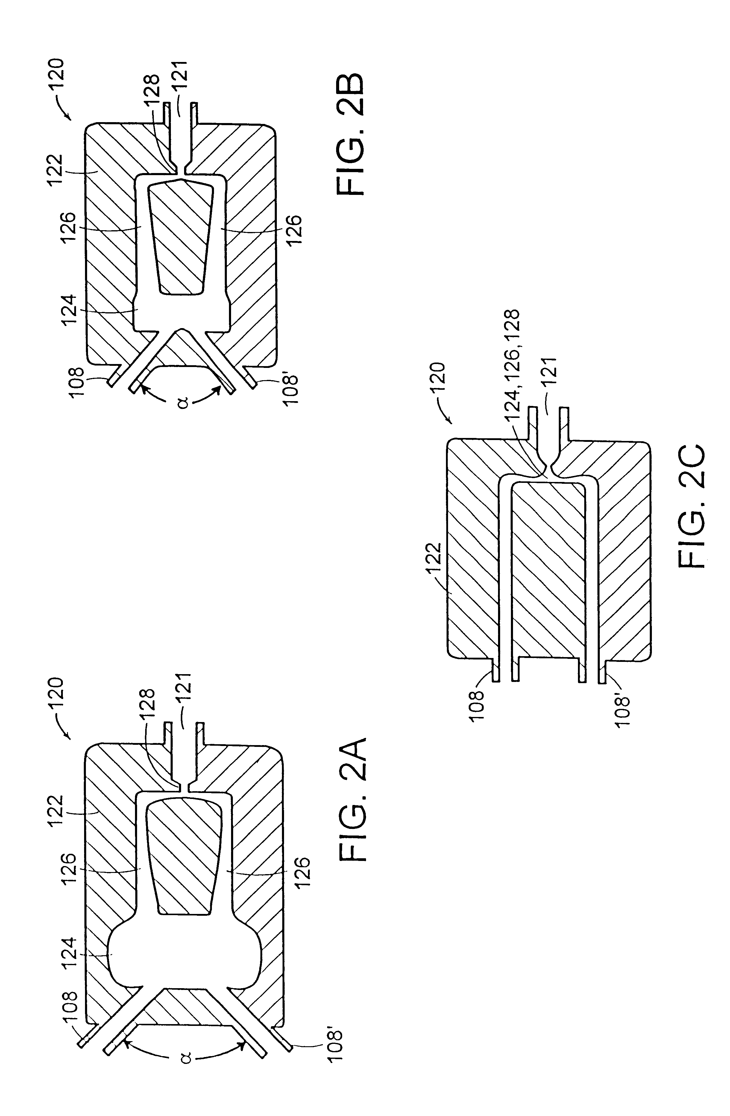
A solution containing sodium silicate and a small amount of aluminum (2.68 mol Si / liter, 0.048 mol Al / liter, 5.76 mol Na / liter) was added to the reservoir of the first pump. A solution of Al.sub.2 (SO.sub.4).sub.3 (1.40 mol Al / liter) was added to the reservoir of the second pump. These solutions at ambient temperature were pumped at 14-15 kpsi operating pressure, at 290-300 ml / minute each, in the high pressure dual stream reactor (FIG. 2C). The product discharged at the exit of the chamber had a pH of 7.2 and was a thick, white gel. This gel was washed with distilled, de-ionized water to remove sodium sulfate salts, filtered, and subsequently dried at 110-120.degree. C. This material was then analyzed by .sup.29 Si NMR. The NMR spectrum is provided in FIG. 9. The .sup.29 Si spectrum consists of a broad peak centered at -87.15 ppm with a half width at half maximum of 14.24 ppm. The Si / Al of the ...

example 3

Synthesis of Aluminosilicate Mullite Precursors Using the Dual Stream Mixer / Reactor According to the Invention

500 ml of a diluted colloidal SiO.sub.2 sol and 2 ml of 30 wt % aqueous ammonia were added to the reservoir of the first pump. To the reservoir of the second pump was added 500 ml of a colloidal Al.sub.2 O.sub.3 sol, undiluted. The atomic Al / Si ratio of the combined solutions was 3:1. These solutions were mixed in the reaction chamber that is shown in FIG. 2C. The solutions were fed at a rate of 300 ml / minute (each), and with a pressure drop of between 10 kpsi and 11 kpsi across the reaction chamber. A viscous, gel-like product was discharged through the outlet of the interaction chamber. This material was recovered and dried at 120.degree. C. without washing. It is referred to as product A.

example 4

Precipitation of Cu / Zn / Al Hydroxycarbonate with 25% Al and Cu / Zn=3.0 Using the Dual Stream Mixer / Reactor of the Invention

A solution comprising 0.35 M Al(NO.sub.3).sub.3.9H.sub.2 O, 0.80 M Cu(NO.sub.3).sub.2.2.5H.sub.2 O, and 0.27 M Zn(NO.sub.3).sub.2.6H.sub.2 O was added to the reservoir of the first pump and a solution containing 3.3 M NaHCO.sub.3 was added to the reservoir of the second pump. The temperature of both solutions was maintained at 60.degree. C. The pump pressures were equal to 15 kpsi during operation, corresponding to a flow rate of 300 ml / min for each pump. The collected slurry product was mixed in a stirred vessel at 60.degree. C. for at least 1 hour (aging). Then, the solids were filtered, washed with water to remove sodium and nitrate ions, and dried at 95.degree. C. An X-ray powder diffraction pattern of the solid product is presented in FIG. 11A and shows that the solid product is pure hydrotalcite, without any malachite impurity.


PUM

PropertyMeasurementUnit
pressureaaaaaaaaaa
velocityaaaaaaaaaa
pressuresaaaaaaaaaa

Abstract

Enhanced macromixing, mesomixing, and micromixing of multiple discrete reactant streams, particularly for precipitation reactions of low density pumpable fluids, are obtained by controlled continuous high pressure multiple reactant streams flowing into a chemical mixer / reactor. Individual reactant streams are pressurized to about 8,000 to 50,000 psi and achieve velocities up to about 250 meters / second in the final stage of the chemical mixer / reactor. Reactant flows are controlled by a combination of a fixed restriction and a variable driving pump.

Description

The present invention is directed to a continuous high pressure multiple discrete stream chemical mixer / reactor and its use, particularly for performing irreversible reactions, e.g. precipitation and nucleation reactions.If multiple streams of chemical reactants are combined with less than optimum mixing, less than acceptable output product compositions may result. Examples of such compromised output products include non-uniform seed precipitation products, incompletely reacted source materials, isolation of unreacted source material by reacted product, liquid striation, and the like. Mixing effects are particularly significant in high reactivity or low diffusivity systems where concentration inhomogeneities cannot be leveled off before appreciable reaction occurs. Some reactions in low viscosity systems are fast enough, relative to conventional mixing, that conversion occurs in a region or reaction zone where partial segregation of the reactants causes steep concentration gradients...

Claims


Application Information

Patent Timeline
Patent Type & Authority Patents(United States)
IPC IPC(8): B01J4/02B01J19/00B01J14/00C01F11/18C01F11/46C01F11/00C01B13/36B01J23/76B01J23/80B01F3/08B01F5/02B01J3/00B01J19/26C01B33/26C01G1/02C01G9/00
CPCB01F5/0256B01J3/00B01J4/02B01J14/00B01J19/0093B01J19/26B01J23/80C01B13/36C01B13/363C01B33/26C01F11/181C01F11/462C01G1/02C01G9/006B01F3/08B01F13/0059B01J2208/00672B01J2219/00162B01J2219/00164B01J2219/00889B01J2219/00891C01P2002/22C01P2002/72C01P2004/38C01P2004/52C01P2004/61C01P2004/62B01F23/40B01F25/23B01F33/30
Inventor THUMM, JEFFREY R.LENTO, MICHAEL A.HIGGINS, JEROME S.
Owner MICROFLUIDICS INT
Why Eureka
Try Eureka