Process and device for manufacturing workpieces with non-circular inner or outer contours as well as eccentrically positioned round boreholes and/or journals

Inactive Publication Date: 2001-05-08
IPROTEC MASCHEN UND EDELSTAHLPROD GMBH
View PDF12 Cites 29 Cited by
  • Summary
  • Abstract
  • Description
  • Claims
  • Application Information

AI Technical Summary

Benefits of technology

According to a further invention it is proposed, that the unround complimentary gearwheels are constructed or designed as so-called a double screw gear drive. A double screw gear drive comprises spur gears which however with respect to conventional spur gears exhibit a helix angle of approximately 80.degree., so that the wheels can possess only a single tooth--similar to a single-threaded screw. Double screw gears with unround wheels have hitherto not been known. They have the advantage that they, with respect to the rolling path, make possible the realization of curves with substantial discontinuities. Besides this they are quite simple to manufacture, for example, using a thread cutting cycle upon a lathe and using a tool device for unround processing as herein described. Besides this, double screw

Problems solved by technology

On the other hand, it is a disadvantage of this device, that for each different geometric form or shape and also size a different cam disk set is necessary, from which there follows an increase in investment costs and a corresponding time requirement for equipment change-over.
It is further disadvantageous, that without external adjustment of the cutting insert neither an incrementally split-up chipping nor a calibration of the contour can be carried out.
Therewith however there is associated the serious disadvantage, that the entire contour must be produced in one single cut.
That is, when the work tool unit is moved radially relative to the workpiece, this leads essentially to either a formation of sharply pointed edges or rounding off of the edges of the contour, so that a fine adjustment of the diameter or a segregation into multiple cuts in this way is not possible.
From this there results that in part very thick cutting chips are produced, from which not only a frequent breaking of the work tool must be expected but rather also an unclean or unsmooth processing surface.
In the proposed process there is the disadvantage, that by the feed of the orbiting work tool tip along a helix lying up

Method used


Image

  • Process and device for manufacturing workpieces with non-circular inner or outer contours as well as eccentrically positioned round boreholes and/or journals
  • Process and device for manufacturing workpieces with non-circular inner or outer contours as well as eccentrically positioned round boreholes and/or journals
  • Process and device for manufacturing workpieces with non-circular inner or outer contours as well as eccentrically positioned round boreholes and/or journals

Examples


Embodiment Construction

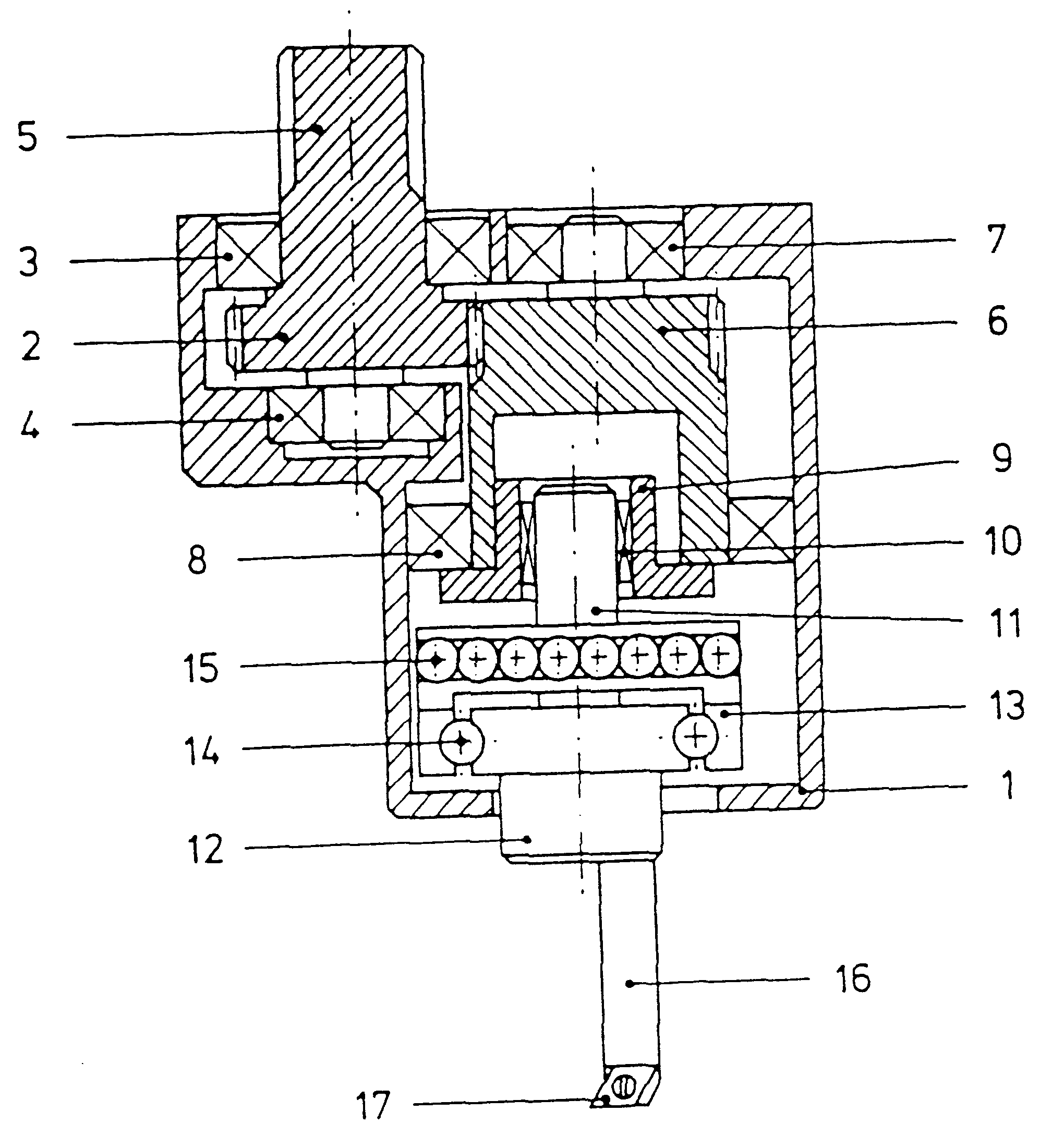
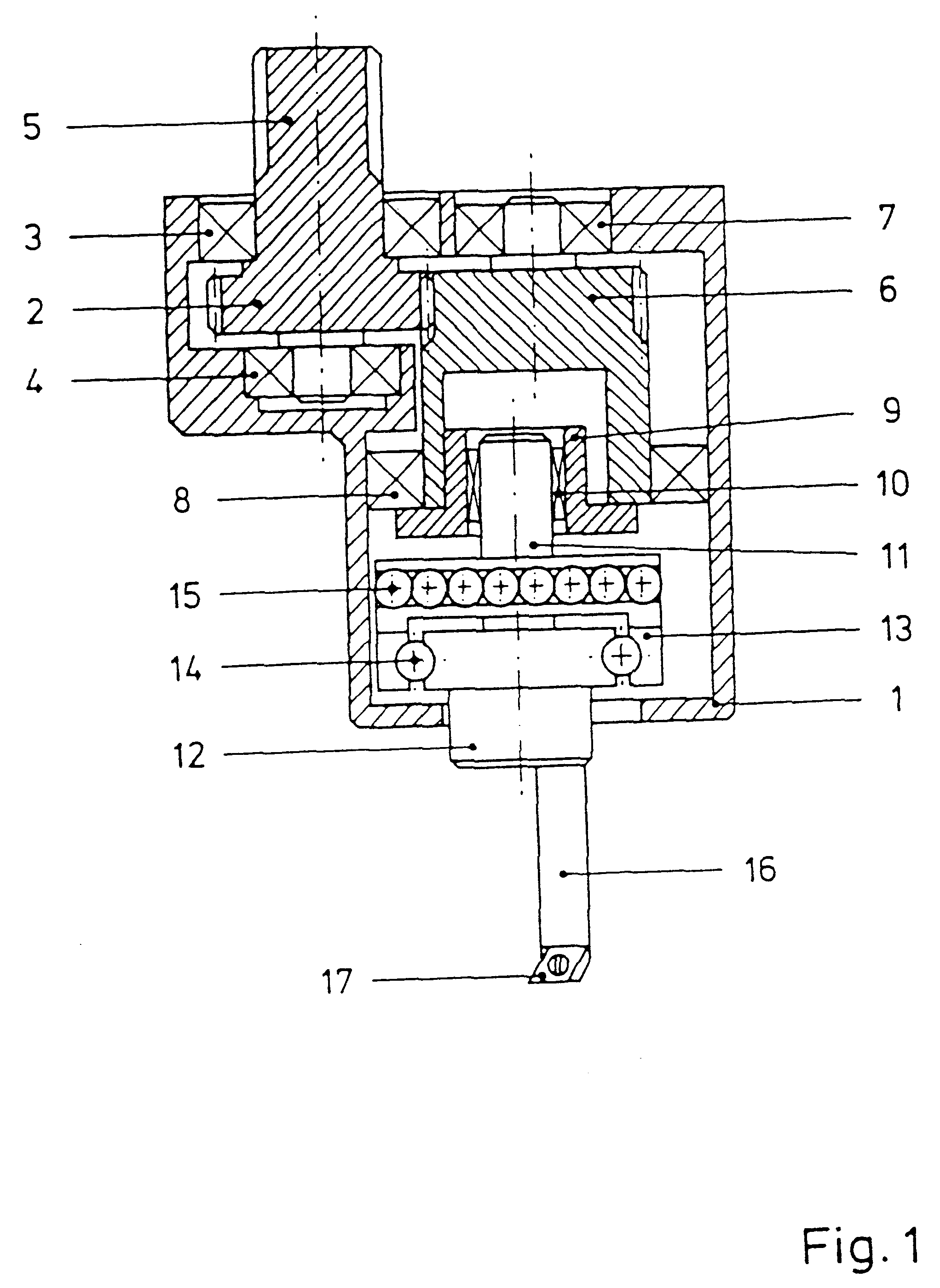
The work tool unit shown in FIG. 1 is comprised of a housing 1, in which the drive pinion 5 is rotatably mounted by means of two roller bearings 3, 4. The side of the drive pinion facing the housing is provided with a gearwheel 2, while the other side is provided with teeth, which are provided for coupling to the machine side drive means. The further connection elements for coupling to the drive on the machine side were omitted. The gearwheel 2 engages in the teeth of a driver 6 rotatably mounted in roller bearings 7, 8, in such a manner that a rotational movement is transmitted to it. In a practical construction embodiment these gearwheels are provided as changeable gearwheel sets, whereupon a constructional freedom is made possible, by determination of the relationship of the number of teeth, to determine the internal transmission ratio or, as the case may be, by the employment of unround complimentary gearwheels, for the realization of a speed variation of the work tool tip as ne...


PUM

PropertyMeasurementUnit
Forceaaaaaaaaaa
Angleaaaaaaaaaa
Volumeaaaaaaaaaa

Abstract

The invention pertains to a special process and devices for the production preferably by machining of workpieces with non-circular outer and inner contours such as squares, hexagons, ellipses, polygons and the like, or eccentric circular bores and/or tappets. In the claimed process, the workpiece is rotated at constant angular velocity while a tool (e.g. the blade of a lathe tool) set eccentrically in relation to the workpieces if moved without rotating about is own axis at controllable speed in a circular path, workpiece and tool being moved towards one another in cycles with the appropriate advance. This ensures that apart from a small cuttings volume far each advance, very narrow tolerances can be set.

Description

BACKGROUND OF THE INVENTION1. Field of the InventionThe invention concerns a special process and a corresponding device for preferably machining production of workpieces with unround inner and / or outer contours, in particular eccentrically positioned round boreholes and / or journals. Unround contours such as, for example, squares, hexagons, ovals, ellipses or polygons as bore holes or on journals are necessary in the industry for the most diverse applications and in the most varied geometries. Generally known and broadly utilized are, for example, internal hexagons in the heads of screws. For the machining of such screws one could consider essentially shaping processes such as, for example, cold- or warm-press extrusion, since with these processes it is possible to produce pieces with a useable outer surface and at the lowest possible cost per unit. The situation is different when a smaller number of parts are required, or when the respective component cannot be produced by this type...

Claims


Application Information

Patent Timeline
IPC IPC(8): B23Q27/00B23Q1/54B23Q1/25B23B29/034B23B41/04F16H35/02
CPCB23Q1/5456B23Q1/5468B23Q1/5481B23Q27/00F16H35/02Y10T82/147Y10T82/10Y10T82/16704Y10T82/128Y10T82/16639Y10T82/122F16H2035/003
Inventor HORMANSDORFER, GERDLEY, HANSWESTERTEICHER, WOLFGANG
Owner IPROTEC MASCHEN UND EDELSTAHLPROD GMBH
Why Eureka
Try Eureka