Axial force null position magnetic bearing and rotary blood pumps which use them

a magnetic bearing and axial force technology, which is applied in the direction of positive displacement liquid engine, piston pump, prosthesis, etc., can solve the problems of limited radial bearing stiffness, rotors of these devices are subject to either radial or axial displacement, and none of these or other fully magnetic suspension blood pumps have proved clinically successful

Inactive Publication Date: 2001-05-08
JARVIK ROBERT
View PDF9 Cites 231 Cited by
  • Summary
  • Abstract
  • Description
  • Claims
  • Application Information

AI Technical Summary

Benefits of technology

In the bearing system shown in FIG. 6 the thrust bearing surfaces also carry tilting loads which are applied to the rotor. In this layout, which uses attracting pairs of magnets at each end of the rotor, the polarity need not be north / south exactly as shown, so long as the two pairs attract. Other arrangements of magnets such as the one shown in FIG. 7 may be used, where repulsion rather than attraction occurs between the magnetic components at either end of the rotor. In FIG. 7, the rotor carries two axially magnetized ring magnets 90,92. The stationary frame of the device carries two other ring magnets 94,96 which are smaller such their outside diameter is approximately equal to the inside diameter of rotor magnets 90, 92. An adjustment screw 98 attached to magnet 96 and threaded through a hole in the frame at 100 permits the magnetic axial forces on the rotor to be balanced.

Problems solved by technology

Olsen U.S. Pat. No. 4,688,998, and Moise U.S. Pat. No. 4,779,614 utilized sensors and servo-control systems of the general type described to obtain full magnetic suspension, however none of these or other fully magnetically suspended blood pumps has proved clinically successful due to their large size and complexity or to other unsolved problems.
The magnitude of the magnetic forces and size of the gaps across which they are exerted limits the stiffness of the radial bearing and the rotors of these devices are subject to either radial or axial displacement due to blood flow and pressure forces as well as shock, vibration and other inertial forces.

Method used


Image

  • Axial force null position magnetic bearing and rotary blood pumps which use them
  • Axial force null position magnetic bearing and rotary blood pumps which use them
  • Axial force null position magnetic bearing and rotary blood pumps which use them

Examples


Embodiment Construction

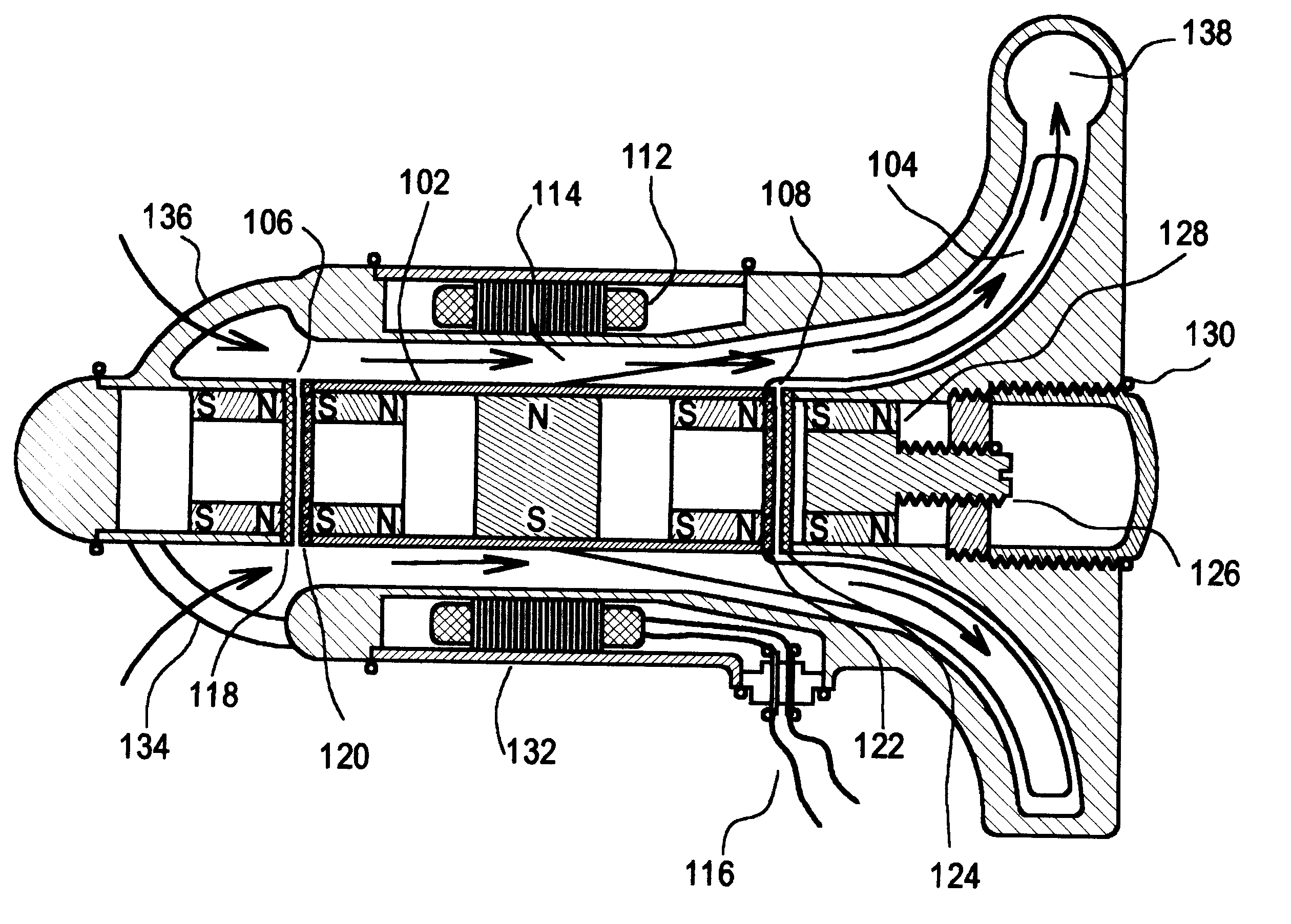
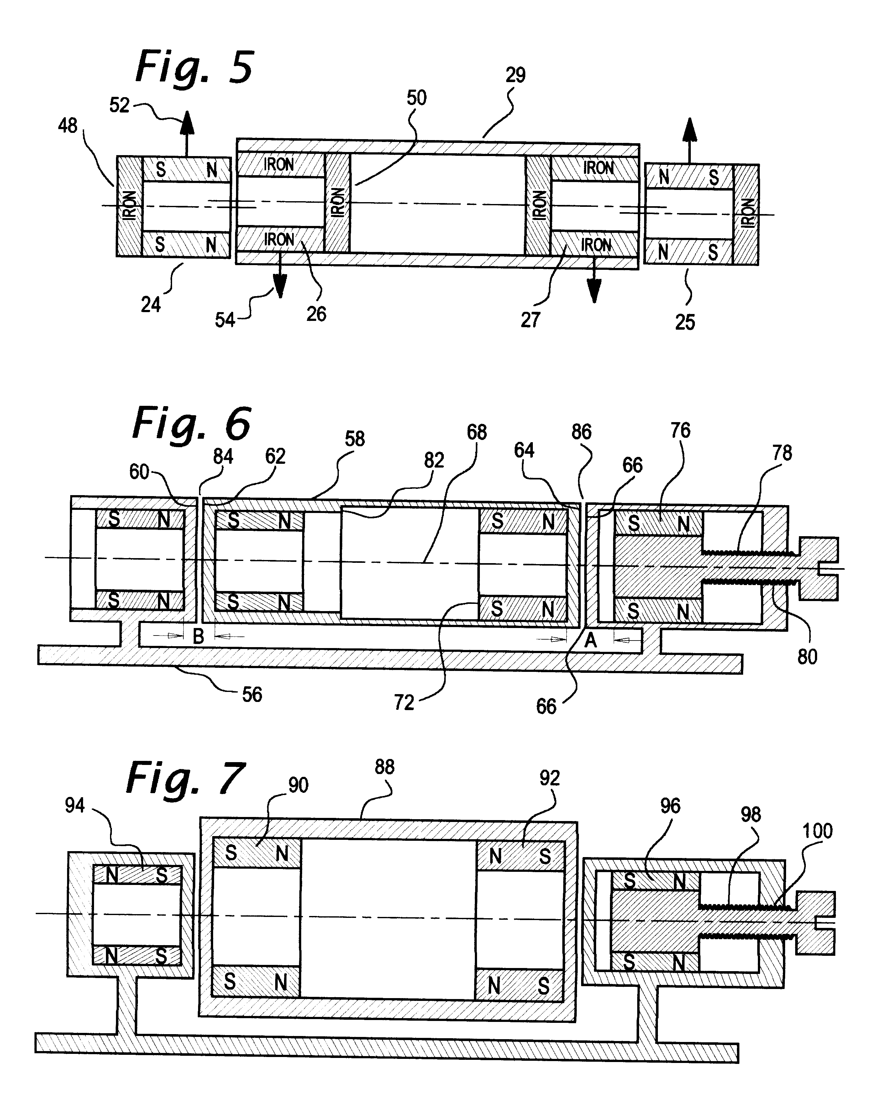
FIGS. 8 & 9 illustrate the preferred embodiments of the invention in which axial force null position magnetic bearings are used to radially suspend the rotors of centrifugal and axial flow blood pumps. Referring to FIG. 8, a magnetic bearing arrangement similar to that shown in FIG. 6 supports a rotor 102, with a centrifugal pump impeller 104, by two pairs of ring magnets at each end of said rotor generally indicated at 106 and 108. A permanent magnet 110 utilized as part of a two pole electric motor which drives the impeller is magnetized side to side as illustrated. It is located midway on the impeller to maximize its separation from the magnetic bearing components at each end so that the magnetic forces of interaction between the motor magnet and bearing magnets will be low. A motor armature 112, having laminations and coils is disposed around the rotor and a annular channel 114 through which blood flows occupies the space between the said armature and the rotor. An electric cabl...


PUM


Abstract

A generally cylindrical rotor very closely confined between two rigid thrust bearing surfaces is radially suspended by an array of attracting or repelling magnets or by a combination of permanent magnets and ring shaped members composed of ferromagnetic material. The geometry permits very small spacing between magnetic components to achieve high radial stiffness. High magnetic axial forces exerted between the rotor and stationary component on one end of the rotor are counter-balanced by equal and opposite forces at the other end of the rotor. Precise positioning of the rotor in the location where the opposing axial magnetic forces counterballance each other yields a net magnetic axial force on the rotor of near zero, hence the reference to this as the null position. Wear resistant mechanical thrust bearings confine the rotor axially to maintain this position during rotatioin. Precisely balance the magnetic axial forces in the proper geometry with relation to the mechanical thrust bearings. Blood pumps utilizing this type of bearing are disclosed, including both axial flow pump and centrifugal flow pump configurations with high flow washing of the junction of the rotating and stationary parts to prevent thrombus accumulation.

Description

Rotary blood pumps having magnetically supported or partially magnetically supported bearings have advantages including low wear, low thrombogenicity, and long durability. The inventors of prior art devices have generally sought to suspend a rotating impeller utilizing various types of sensors and feedback control methods similar to those used with general purpose magnetically suspended bearings. The objective of completely magnetically suspended blood pumps has been to provide wide clearance gaps between the rotating impeller and other parts of the device so that blood could flow through the gaps to avoid stagnation and clotting. Complete elimination of contact between rotating and stationary parts has the advantage of avoiding friction and heat generation which can damage blood. Olsen U.S. Pat. No. 4,688,998, and Moise U.S. Pat. No. 4,779,614 utilized sensors and servo-control systems of the general type described to obtain full magnetic suspension, however none of these or other ...

Claims


Application Information

Patent Timeline
Patent Type & Authority Patents(United States)
IPC IPC(8): A61M1/10F04D13/06F04D29/04A61M60/178A61M60/232A61M60/237A61M60/422A61M60/82A61M60/825F04D29/048
CPCA61M1/101F04D13/0646F04D29/048F16C32/0427A61M1/1015A61M1/1031F16C2316/18A61M60/82A61M60/422A61M60/148A61M60/232A61M60/237A61M60/178A61M60/825
Inventor JARVIK, ROBERT
Owner JARVIK ROBERT
Why Eureka
Try Eureka