
Photocatalyst-carrying structure and photocatalyst coating material

a photocatalyst and coating material technology, applied in the direction of organic compound/hydride/coordination complex catalyst, physical/chemical process catalyst, metal/metal-oxide/metal-hydroxide catalyst, etc., can solve the problems of reducing photocatalytic activity, deteriorating, and affecting the durability of organic materials, so as to improve the adhesive property of the adhesive layer, excellent durability, and the effect of photocatalytic activity

Inactive Publication Date: 2001-05-08
NIPPON SODA CO LTD
View PDF6 Cites 183 Cited by
  • Summary
  • Abstract
  • Description
  • Claims
  • Application Information

AI Technical Summary

Benefits of technology

wherein R.sup.1 is an alkyl having 1-8 carbon atoms which is unsubstituted or substituted with any of amino, carboxyl or chlorine atom, R.sup.2 is an alkyl having 1-8 carbon atoms or an alkoxy-substituted alkyl having 1-8 carbon atoms, n.sup.1 is 0, 1 or 2, n.sup.2 and n.sup.3 are each independently 0 or any of integers of from 1 to 3, n.sup.4 is any of integers of from 2 to 4, provided the sum of n.sup.1, n.sup.2, n.sup.3 and n.sup.4 is 4, can strongly glue a photocatalyst and protect the substrate from photocatalytic action derived from a photocatalyst.
Materials having thermic rays reflecting function and ultraviolet ray blocking function can be incorporated into a sticker layer which is formed on the background of a film to provide such functions. For example, a material like ultraviolet blocking clear coating agent described in "Convertec", March 1996, page 95, is solvent-dispersible type and is applicable for the above purpose. Stickers, such as acryl-type and silicon-containing compounds are normally used, however, it is also feasible to add various types of ultraviolet ray blocking agents and thermic rays blocking agents. Considering spoil caused with the remainning sticker at the time of renewal the photocatalyst carrying film, it is advisable to avoid the use of a sticker having strong binding property. As a method to provide a sticker and a detachable film onto a photocatalyst-carrying film, a method to firstly coat a sticker in solution to the reverse side of the film by means of gravure printing and then dry and roll the coated-film together with detachable polypropylene film while laminating it therewith is simple and may be preferably employed.

Problems solved by technology

However, among the materials as disclosed above, it is reported that the one comprising an organic material as its main component has the disadvantage that the organic material can be decomposed and deteriorated due to catalytic reaction caused by a photocatalyst contained in the said material, and the durability thereof has therefore been problematic (see Pumiaki OotaniO Kobunsi Kako No.42, vol.5, page 18 (1993); "Titanium dioxide", by Manabu Kiyono, published by Gihodo, page 165).
Further, even though the substrate is composed of an inorganic material, such as glass and ceramics, there must be some problems in the durability property of the substrate, such that, if an organic polymer resin is used as an adhesive for carrying a photocatalyst on the substrate, the photocatalytic activity may be lowered due to coverage of the surface of photocatalyst particles with such resin, and that the photocatalyst may be exfoliated from the substrate due to the cause of decomposition and deterioration of said organic polymer resin by virtue of its photocatalytic activity.
However, these methods have a problem that they require a process of baking the substrate at a high temperature in order to obtain production and crystalization of photocatalyst particles over the substrate and adhesive property with the substrate, and therefore, it is difficult to carry photocatalyst over a wide area and the production according to these methods requires very high cost.
However, the adhesive property of a metal oxide sol, such as silica sol, is very weak because it is derived from van der Waars force (see Fine Ceramics, vol.1, page 216-223, 1980) so that the binding strength and durability of the adhesive were insufficient.
Further, the method additionally requires a process of baking at a high temperature, and therefore, it was not applicable for all types of substrates including commonly used types of resins which are easily decomposed by heating.
However, no report has been made up till now describing that a substrate having excellent adhesive property and durability while keeping the high photocatalytic activity of a photocatalyst which is uniformly distributed in a metal oxide sol as described above is obtained.
However, the price of fluororesin is high, and it is required to cover the most of the surface of photocatalyst particles with fluororesin in order to stick photocatalyst particles strongly.
Although an example that intends to carry a photocatalyst onto a substrate by means of mixing the photocatalyst with a binder resistant to decomposition, such as fluororesins and poly(organosiloxane), has been known (see EP-0633064), it is not sufficient to solve practically such problems as to adhesive property and durability.

Method used


Image

  • Photocatalyst-carrying structure and photocatalyst coating material
  • Photocatalyst-carrying structure and photocatalyst coating material

Examples


example 19

Use of Titania Sol

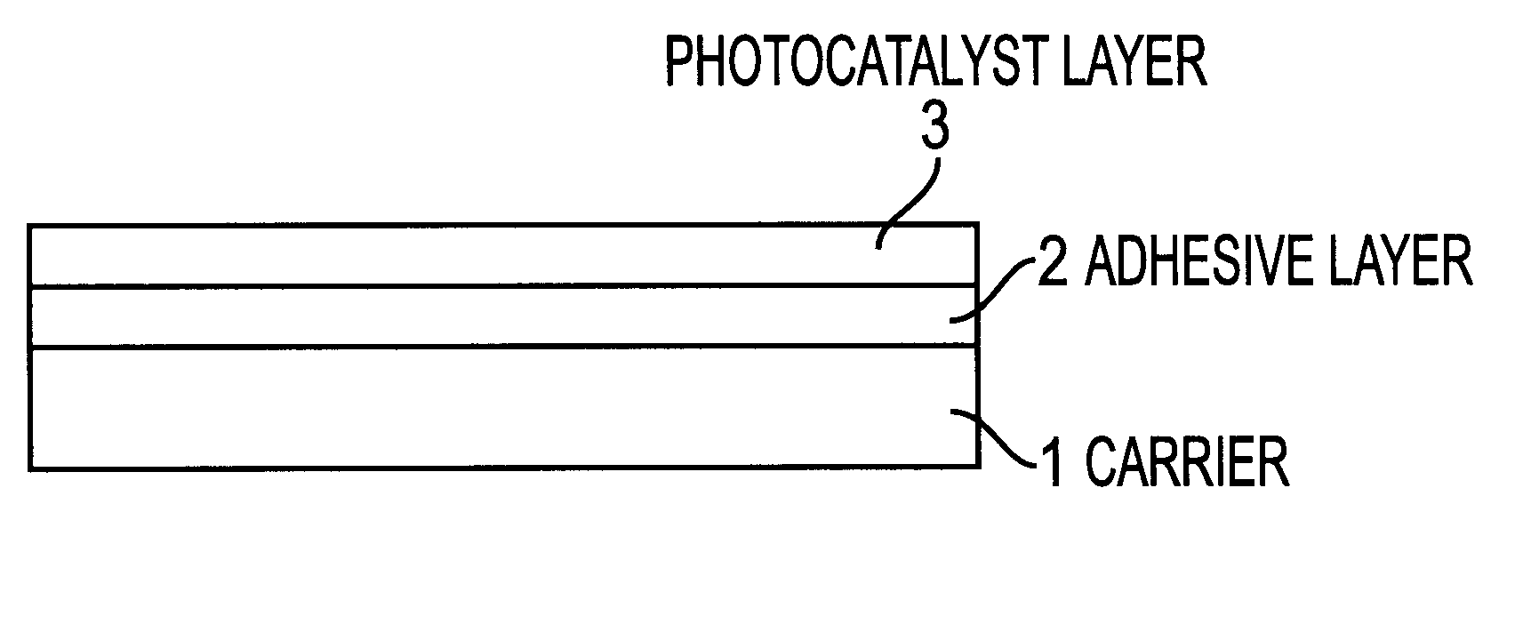
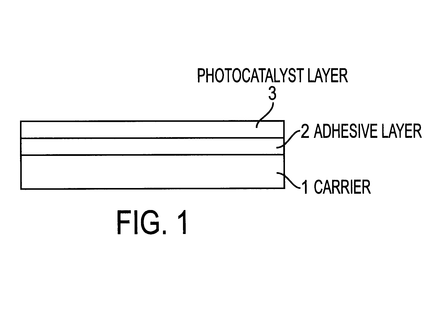
A coating material to be used for forming a photocatalyst layer was prepared by adding and dispersing titania sol containing 12% by weight of titanium dioxide and acidified with nitric acid, which is a substitute of fine granule titanium dioxide (P-25) manufactred by Nihon Aerozil Co., Ltd., into silica gel (Trade name: Cataloid SI-30, Manufactured by Shokubai Kasei Co., Ltd.) being adjusted to pH 1.5 and then further adding a surfactant. Whereas, a solution to be used for an adhesive layer was prepared by adding polymethoxy siloxane (PS-2) into a resin solution used in the example 10 at a rate such that the content of silicon oxide in a dried adhesive layer becomes 35% by weight.

The solution for forming an adhesive layer was applied by using a baker applicator onto a soda lime glass substrate with a thickness of 1 mm and a dimension of 7 cm.times.7 cm, and the coating material for forming a photocatalyst layer was also applied by using bar coater onto the same sub...

example 20

Use of Silica-alumina Sol

A photocalyst-carrying structure was prepared by using the same materials and according to the same method as described in the example 19 except replacing silica sol used in the example 19 with a mixed sol solution consisting of alumina sol manufactured by Nissan Chemical Industries Co., Ltd. and silica sol.

The photocatalyst-carrying structure obtained was found to have high adhesive property and photocatalytic activity.

example 21

Coating According to Gravure Printing Method

By using gravure printing system, the solution for forming an adhesive layer and the solution for forming a photocatalyst layer were applied onto a polyester film (Trade name: Cosmoshine A4100) manufactured by Toyobo Co., Ltd. at a speed of 10 m / min. and at dry zone temperature of 130.degree. C. such that the thickness of each layers become 3 .mu.m, respectively. For the printing, a microgravure coater with a width of 70 cm manufactured by Yasui Seiki Co., Ltd. was used.

The photocatalyst-carrying structure obtained was found to have very high whole light transmittance of 95%.


PUM

PropertyMeasurementUnit
Percent by massaaaaaaaaaa

Abstract

The present invention provides a photocatalyst-carrying structure which has a structure, wherein an adhesive layer is provided in between a photocatalyst layer and a substrate, the adhesive layer is composed of silicon-modified resin, polysiloxane-containing resin or colloidal silica-containing resin, and for forming the photocatalyst layer a composition comprising a metal oxide gel or a metal hydroxide gel and a photocatalyst is used. Further, the present invention also provides a photocatalyst coating agent for producing a photocatalyst-carrying structure which contains silicon compound, at least one metal oxide sol or metal hydroxide sol, and at least one photocatalyst powder or sol.

Description

The present invention is related to a structure carrying a photocatalyst which is useful for antifouling, cleaning water, deodorization, pasteurization, a treatment of waste water, decomposition of water, a control of algae growth and various chemical reactions.Titanium dioxide, which is n-type semiconductor, has been known as a photocatalyst that activates various chemical reactions with ultraviolet radiation energy, such as chemical reactions resulted in during a process of decomposition of water, deodorization, pateurization, cleaning of water, a treatment of waste water or the like. It is said that the catalytic activity of a photocatalyst can be generally high when it is used either in powder form or in a form of suspension in a solvent, however, in many cases, such photocatalyst is practically obliged to be used in a form being carried on a certain substrate. For utilizing ultraviolet radiation energy from light efficiently, it is advantageous to make a substrate into a shape ...

Claims


Application Information

Patent Timeline
IPC IPC(8): B01J35/00C03C17/42B01J37/02B01J37/03
CPCB01J35/002B01J37/0219B01J37/0225B01J37/036C03C17/42B01J35/004Y10T428/258C03C2217/445C03C2217/45C03C2217/477C03C2217/478C03C2217/71Y10T428/259Y10T428/257Y10T428/256Y10T428/31667Y10T428/31663Y10T428/31612B01J35/30B01J35/39
Inventor KIMURA, NUBUOABE, SHINJIYOSHIMOTO, TETSUOFUKAYAMA, SHIGEMICHI
Owner NIPPON SODA CO LTD
Learn More