Resin-sealed electronic apparatus for use in internal combustion engines

Inactive Publication Date: 2001-07-10
HITACHI LTD +1
View PDF8 Cites 43 Cited by
  • Summary
  • Abstract
  • Description
  • Claims
  • Application Information

AI Technical Summary

Problems solved by technology

These requirements are not met by the prior art one-chip IC package module discussed above.
With high-temperature Pb--Sn alloy-based solder materials (Pb:Sn=90:10) that have traditionally been employed as

Method used


Image

  • Resin-sealed electronic apparatus for use in internal combustion engines
  • Resin-sealed electronic apparatus for use in internal combustion engines
  • Resin-sealed electronic apparatus for use in internal combustion engines

Examples


Embodiment Construction

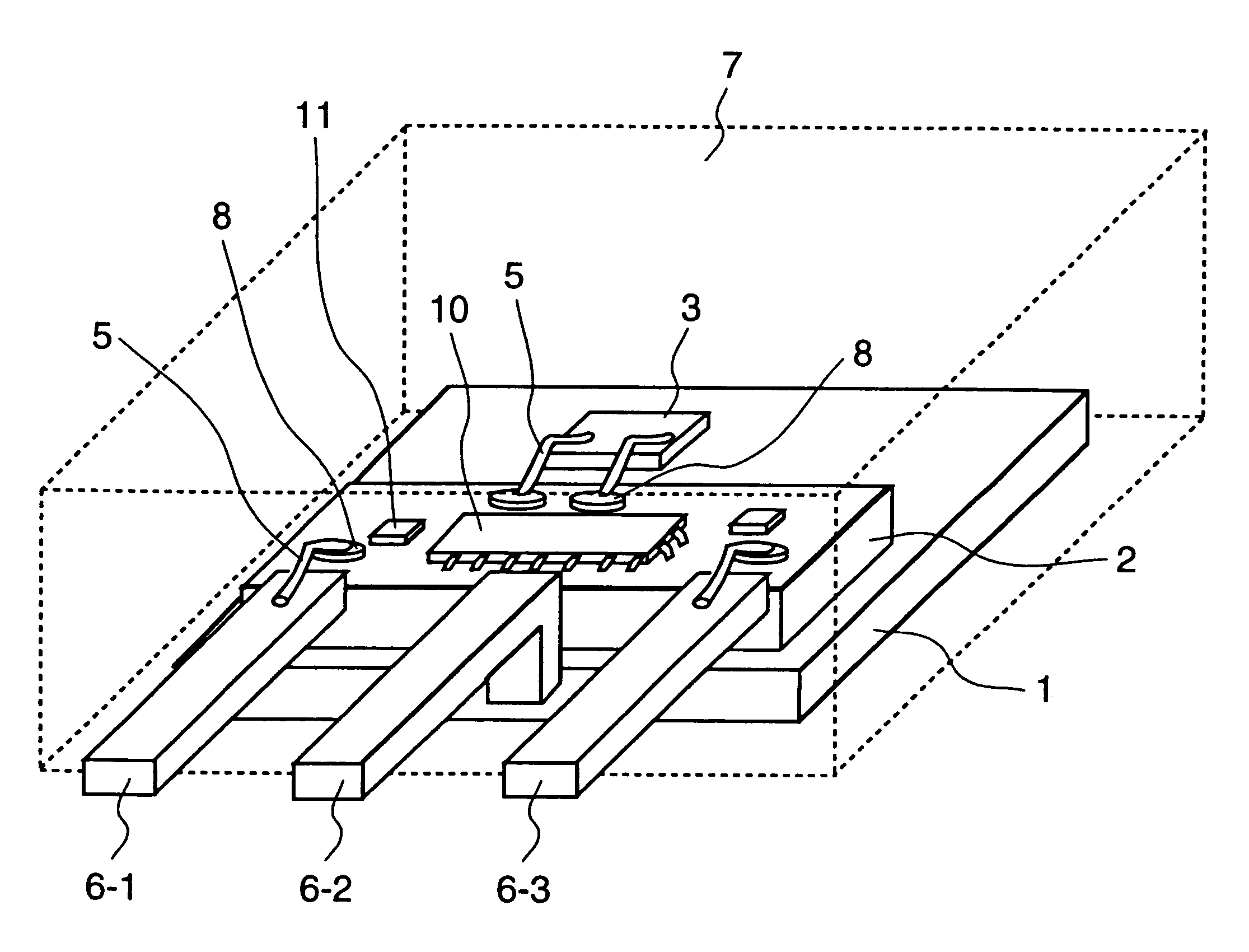
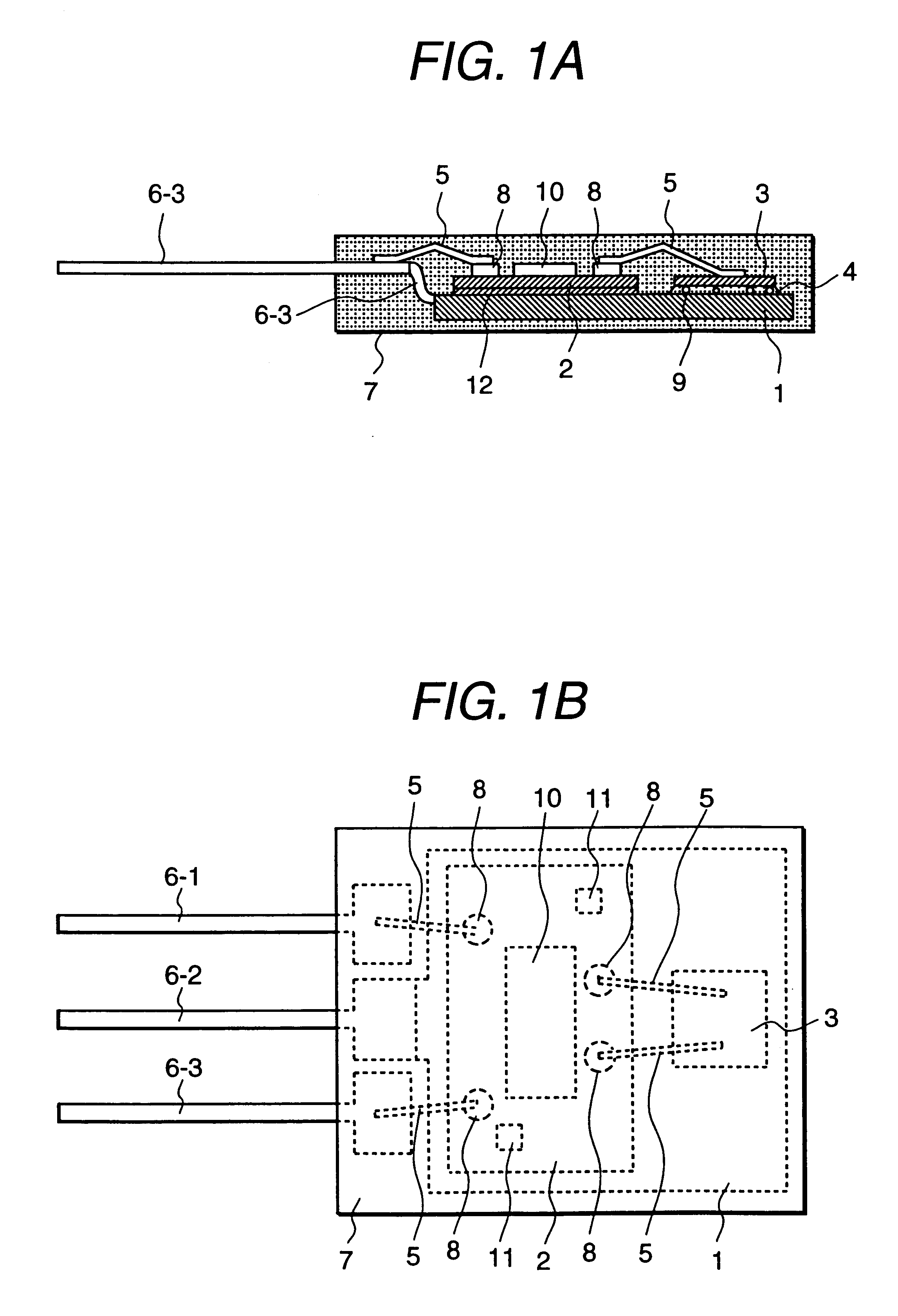
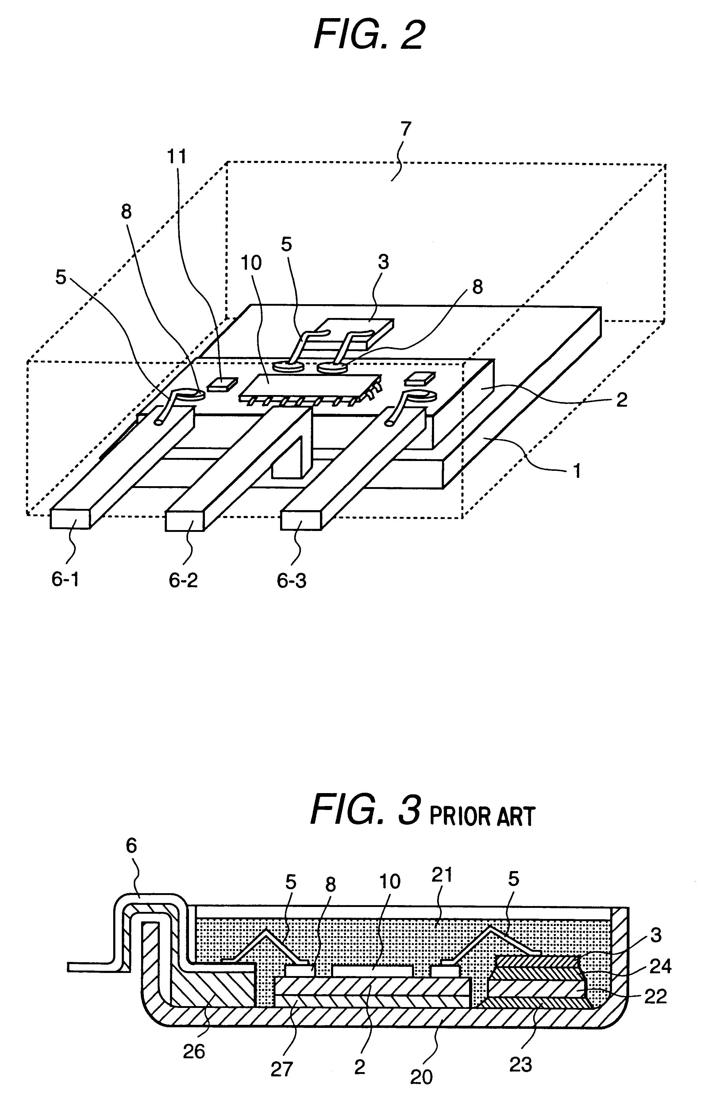
One preferred embodiment of the present invention will now be explained with reference to the accompanying figures of the drawing. FIG. 1A, FIG. 1B and FIG. 2 illustrate one exemplary igniter device as one example of resin-sealed electronic apparatus for use in internal combustion engines in accordance with one embodiment of this invention, wherein FIG. 1A depicts a side sectional view of the embodiment and FIG. 1B shows its plan view whereas FIG. 2 shows its plan view with an outer package housing eliminated for illustration purposes only.

In the drawings, reference numeral "1" is used to designate a heat sink that is made of either copper or aluminum; numeral 2 denotes a hybrid IC substrate (hybrid circuit board); 3 indicates a power semiconductor device.

Several parts or components that make up the required functions of the igniter are mounted (secured) on the substrate 2, which include a hybrid IC 10, chip capacitor 11, MIC and others. The power semiconductor device 3 is for use a...


PUM


Abstract

A less-deformable resin-sealed electronic apparatus of high reliability capable of increasing the robustness (long life-time) of soldered portions of a power semiconductor device for use in internal combustion engines while increasing the physical stiffness of an overall apparatus structure for achieving enhanced resistance to flexure or bending stresses is provided. A hybrid IC substrate 2 and power semiconductor device 3 are mounted on a metallic heat sink 1. The power semiconductor device 3 is coupled and contacted with the heat sink 1 by use of an Sn-Sb alloy-based solder material 4. The power semiconductor device 3 and hybrid IC substrate 2 plus heat sink 1 as well as input/output terminals 6-1 to 6-3 are embedded in a package 7 except for part of the input/output terminals, which package is made of epoxy at 70 to 90 weight percent (%) of an inorganic loading or filler material as machined by transfer mold techniques.

Description

1. Technical Field of the InventionThe present invention relates generally to electronic apparatus including, but not limited to, electronic ignition devices (igniters) for use in internal combustion engines as mounted within engine room spaces of land vehicles, and more particularly to electronic devices having resin-sealed package structures.2. Prior ArtOne prior known structure of a semiconductor package for use in internal combustion engines, in particular, igniter modules, has been disclosed in Japanese Patent No. 2590601.The prior art igniter package structure as taught thereby is designed so that a printed circuit board and a power transistor are integrally packed by transfer mold techniques using synthetic resin together with a heat release plate, known as a heat sink. In this prior art the power transistor packed is coupled to the heat sink via a heat spreader and dielectric plate lying therebetween.Another prior art igniter device adapted for internal combustion engines is...

Claims


Application Information

Patent Timeline
IPC IPC(8): H01L23/495H01L23/48H05K3/28H05K3/34H05K1/09F02P15/00H01F38/12H01L23/29H01L23/31H01L23/40H01L25/07H01L25/18
CPCH01L23/49562H05K3/284H05K3/3463H01L2924/1305H01L24/45H01L2224/73265H01L2224/45124H01L2924/01068H01L24/48H05K1/092H01L2924/19041H01L2924/14H01L2924/13055H01L2924/01078H01L2224/48091H01L2224/48247H01L2224/48472H01L2924/00014H01L2924/00H01L2924/181H01L2924/00012
Inventor KAMINAGA, TOSHIAKIFUKATSU, KATSUAKIKOBAYASHI, RYOICHI
Owner HITACHI LTD
Why Eureka
Try Eureka