
Method and apparatus for NOx reduction in flue gases

a technology of flue gas and reduction method, which is applied in the direction of lighting and heating apparatus, combustion types, separation processes, etc., can solve the problems of undesirable nitrogen oxide generation and emission, the implementation of conventional reburn technology requires a relatively tall furnace, and many furnaces in the united states do not have the internal volume required for retrofitting this technology

Inactive Publication Date: 2001-07-10
GAS RES INST
View PDF22 Cites 31 Cited by
  • Summary
  • Abstract
  • Description
  • Claims
  • Application Information

AI Technical Summary

Benefits of technology

The method of this invention results in higher NO.sub.x reductions than either natural gas reburn or selective non-catalytic reduction, and at a lower cost. The process is well matched to the NO.sub.x reduction requirements of ozone non-attainment areas where reductions greater than 75% from uncontrolled levels may be required. Natural gas reburn or selective non-catalytic reduction alone cannot achieve such a level of NO.sub.x control. The method of this invention also offers a flexible approach which is ideal for seasonal NO.sub.x control. Raw natural gas injection with controlled mixing can be used when up to 50% NO.sub.x reduction is required. The nitrogenous compound may be co-injected with natural gas during summer when greater NO.sub.x reductions are required. The chemistry of the method of this invention occurs over a wider temperature window than the selective non-catalytic reduction process. In addition, the method requires less natural gas than standard reburn. Capital costs are also lower than standard reburn because flue gas recirculation and overfire air duct work are not required. Because the nitrogenous compound may be co-injected with the fluid fuel, the use of a carrier medium is optional. Finally, there is a reduced risk of ammonia or other reagent leakage or ammonium sulfate or related deposit formation because the fluid fuel and nitrogenous compound injection occurs at higher temperatures than selective non-catalytic reduction.

Problems solved by technology

The generation and emission of nitrogen oxides are undesirable because they are toxic.
Furthermore, due to the requirement of at least three combustion zones within the furnace, a primary combustion zone, a fuel-rich reburn zone downstream of the primary combustion zone, and a fuel-lean completion zone downstream of the fuel-rich reburn zone, implementation of conventional reburn technology requires a relatively tall furnace.
Unfortunately, many furnaces in the United States do not have the internal volume required for retrofitting this technology.
However, conventional natural gas reburn is expensive due to the capital and operating expenses required for recirculating flue gases and providing overfire air (also known as burn-out air).
In addition, the requirement of a fuel-rich zone suggests the use of greater than 10% natural gas, making conventional gas reburn uneconomical for most coal-fired furnaces.
Because coal has inherent bound nitrogen which can be oxidized to NO, the use of coal as a reburn fuel is limited to initial NO concentrations greater than 200 ppm.
At lower temperatures, the kinetics are too slow and result in high reagent leakage.
Conversely, in the absence of added promoters or modifiers, the lower value of the temperature window is limited to about 1600.degree. F.
At lower temperatures, the rate of reaction of the reducing agents with NO is too slow, thereby resulting in inadequate NO reduction and in "ammonia slip," which, in turn, can result in the deposition of corrosive ammonium bisulfate and ammonium sulfate on the air heater surfaces of boilers.
For coal fired boilers, "smelly fly ash" due to absorption of ammonia on the fly ash is another problem which may be caused by the ammonia slip.
The narrow process temperature window is a drawback to the implementation of the selective non-catalytic reduction process.
Due to the difficulty in maintaining optimum injection temperature conditions, it may result in lower than the maximum possible NO reductions in a number of practical applications.
The shifting nature of the flue gas temperature profile is especially a problem in boilers operating at varying load levels due to electric power dispatch requirements.
However, the practical lower temperature limit of selective non-catalytic reduction operation with CO or hydrocarbon promoters is about 1500.degree. F.-1600.degree. F., below which the rate of oxidation of CO is too slow.
Completion of the reactions at higher temperatures also decreases the chances of "ammonia slip", a by-product of both selective non-catalytic reduction and selective catalytic reduction processes.
The addition of hydrocarbon fuel with nitrogenous additives also has the adverse effect of increasing the emissions (reducing the reduction) of TBN species at higher temperatures (above about 1800.degree. F.).
Natural gas reburn or selective non-catalytic reduction alone cannot achieve such a level of NO.sub.x control.

Method used

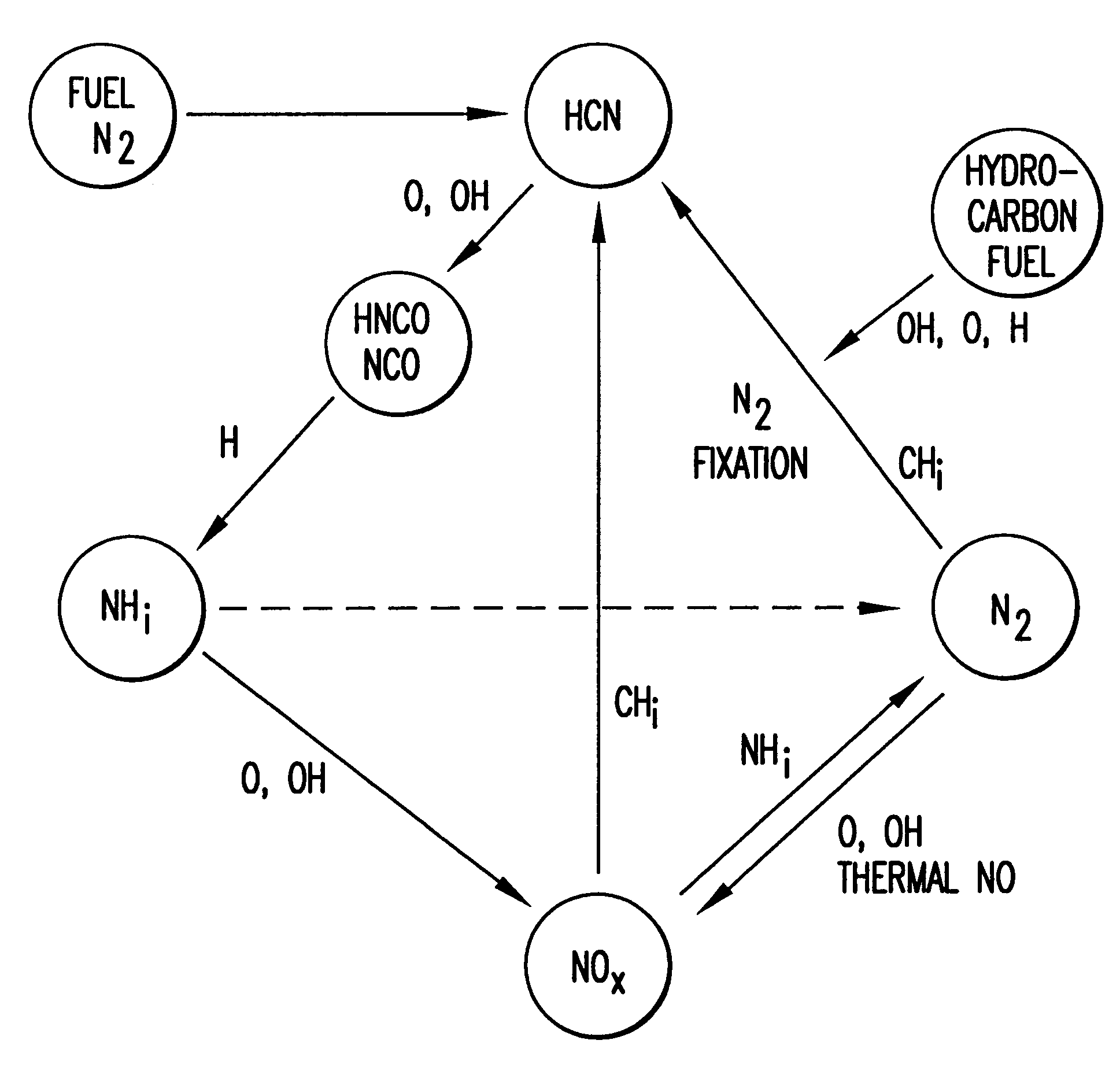
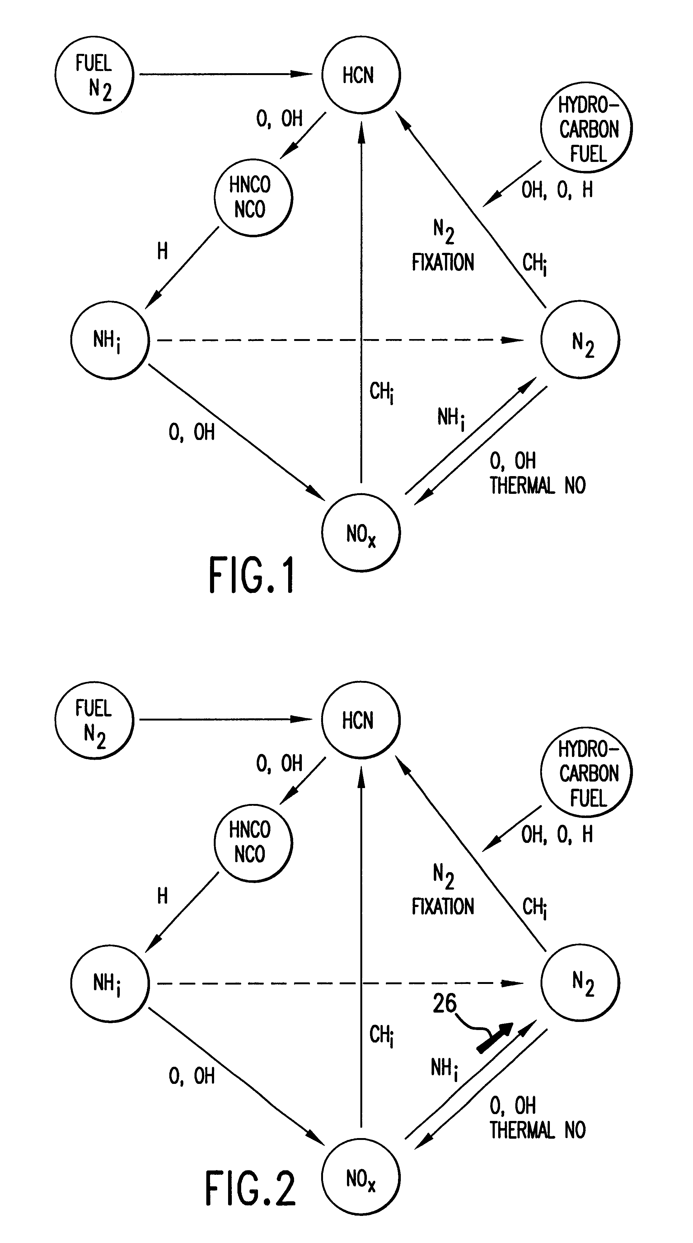
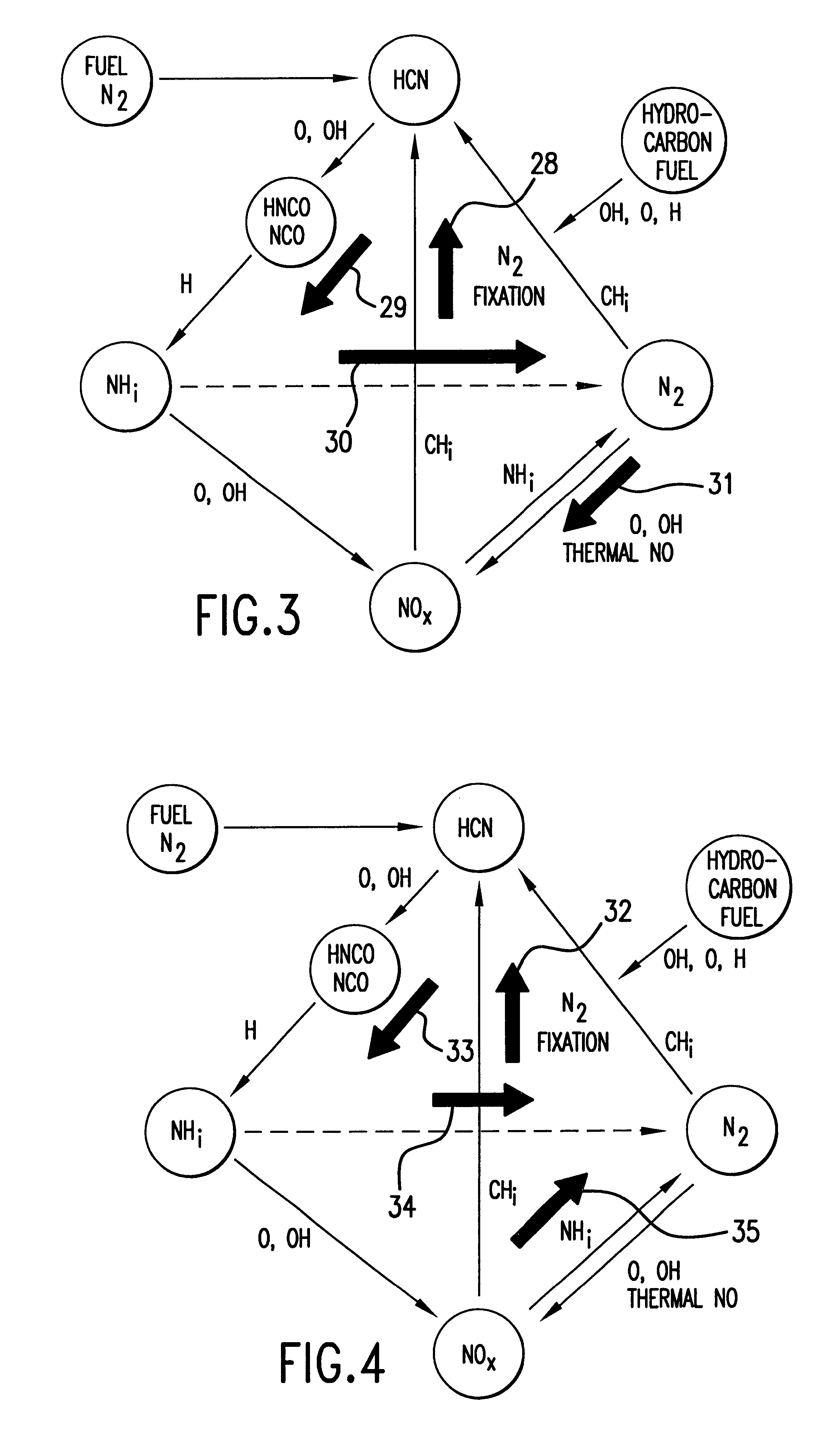

Image

  • Method and apparatus for NOx reduction in flue gases
  • Method and apparatus for NOx reduction in flue gases
  • Method and apparatus for NOx reduction in flue gases

Examples


Embodiment Construction

As shown in FIG. 5, the apparatus for reducing nitrogen oxide emissions in combustion products 10 can be readily retrofitted to a combustion apparatus, such as an existing furnace 12. Furnace 12 for combustion of a carbonaceous material comprises primary combustion zone 16, carbonaceous material inlet means 15 for introducing carbonaceous material into the primary combustion zone, oxidant inlet means 17 for introducing an oxidant into primary combustion zone 16, and flue gas exhaust means 18 for removing flue gases from furnace 12. Although FIG. 5 shows a bottom-fired furnace, it will be apparent to those skilled in the art that the method and apparatus of this invention may be applied to all types of furnaces including tangential fired, wall fired, opposed fired, cyclones, roof-fired and stoker furnaces. Furnace 12 is particularly designed to utilize coal or any other carbonaceous fuel. The fuel enters furnace 12 through carbonaceous material inlet means comprising mills 13 and bur...


PUM

PropertyMeasurementUnit
temperatureaaaaaaaaaa
molar ratioaaaaaaaaaa

Abstract

In a furnace having a primary combustion zone for combustion of a fuel and oxidant, an in-furnace method for reducing nitrogen oxides in combustion products generated in the primary combustion zone in which at least one fluid fuel selected from the group consisting of natural gas, hydrogen, CxHy compounds, CxHyOz compounds and mixtures thereof in an amount in a range of about 2.0% to about 25% of a total heat input to the furnace and at least one nitrogenous compound selected from the group consisting of ammonia, amines, urea, cyanuric acid and mixtures thereof are injected into the furnace downstream of the primary combustion zone, forming an overall fuel-lean NOx-reduction zone.

Description

1. Field of the InventionThis invention relates to a method and apparatus for reduction of nitrogen oxide emissions by industrial heating furnaces, such as utility boilers, fired by carbonaceous fuels, in particular, fuels with fixed nitrogen, such as coal.2. Description of Prior ArtDuring the combustion of fuels having fixed nitrogen, such as coal, oxygen from the air combines with the nitrogen to produce nitrogen oxide (NO). At sufficiently high temperatures, oxygen also reacts directly with atmospheric nitrogen to form nitrogen oxide. A small fraction of the nitrogen oxide formed in the flame is oxidized to nitrogen dioxide (NO.sub.2) downstream of the flame. The total emission of nitrogen oxides, NO+NO.sub.2, is denoted by NO.sub.x. The generation and emission of nitrogen oxides are undesirable because they are toxic. In addition, nitrogen oxides, along with oxides of sulfur (SO.sub.2, SO.sub.3) contribute to acid rain precipitation, and in the presence of sunlight, react with h...

Claims


Application Information

Patent Timeline
Patent Type & Authority Patents(United States)
IPC IPC(8): B01D53/79B01D53/56F23C6/04F23C6/00F23J7/00
CPCB01D53/56B01D53/79F23J7/00F23C6/047F23C2201/101F23C2201/301
Inventor BREEN, BERNARD P.HURA, HARJIT S.
Owner GAS RES INST
Learn More