Particle-free cathodic arc carbon ion source

a carbon ion source and cathodic arc technology, applied in the direction of ion implantation coating, diaphragms, electrodes, etc., can solve the problems of reducing the output plasma flux and hence reducing the complexity of the source, and reducing the deposition rate and system efficiency

Inactive Publication Date: 2001-07-17
MCGILL UNIV
View PDF6 Cites 38 Cited by
  • Summary
  • Abstract
  • Description
  • Claims
  • Application Information

AI Technical Summary

Problems solved by technology

a) a decrease in the output plasma flux and hence in deposition rate and system efficiency;
b) a decrease in the area covered by the beam resulting in smaller surface areas being coated in a given time interval;
c) such systems add to the complexity of the source by imposing a particular source geometry and more importantly an added control of the magnetic/electric field parameters within the filter to be adjusted to the arc source parameters;
d) particles produced by the arc source accumulate in the filter and potentially affect the fi...

Method used


Image

  • Particle-free cathodic arc carbon ion source
  • Particle-free cathodic arc carbon ion source
  • Particle-free cathodic arc carbon ion source

Examples


Embodiment Construction

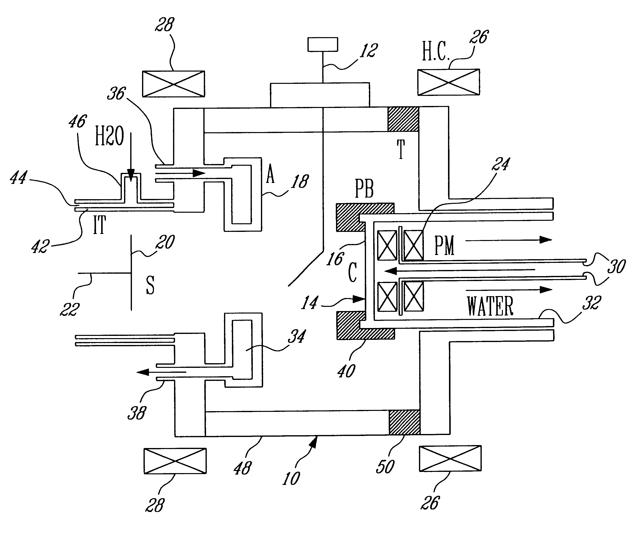
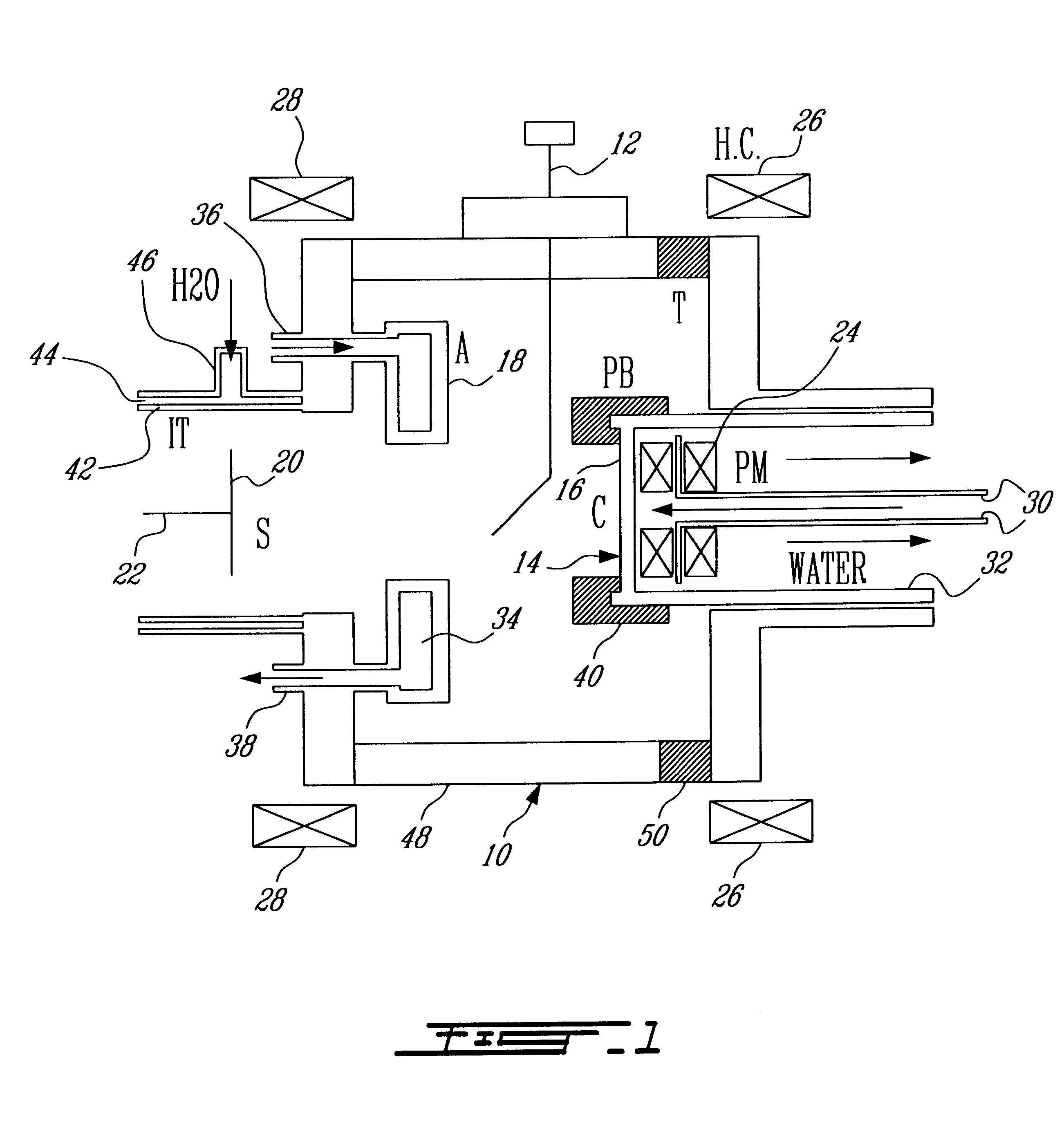
With further reference to FIG. 1 a vacuum chamber 10 is connected to a source of vacuum (not shown). An arc igniter 12 is mounted in chamber 10.

A graphite cathode 14 having a target surface 16 and a generally annular anode 18 are mounted in chamber 10. A substrate 20 to be coated is supported by a holder 22 in opposed facing relationship with target surface 16.

Permanent magnets 24 are disposed behind cathode 14 and Helmholz coils 26 and 28 are disposed radially outwardly of chamber 10.

Cathode 14 is water cooled by water flow along an inner conduit 30 and an outer conduit 32.

Anode 18 is water cooled by water flow along an annular conduit 34 having an inlet conduit 36 and an outlet conduit 38.

Cathode 14 is mounted in an insulating casing 40 which defines a passive border.

Cathode 14 and anode 18 are connected to an arc power supply (not shown).

The tubular wall 42 around substrate 20 may also be water cooled by a flow passage 44 having an inlet 46.

The wall 48 of chamber 10 may include i...


PUM

PropertyMeasurementUnit
Angleaaaaaaaaaa
Angleaaaaaaaaaa
Angleaaaaaaaaaa

Abstract

A method and apparatus for vacuum arc deposition of carbon on a substrate inhibits or eliminates emission of contaminating carbon particles in the ion plasma by maintaining an elevated local plasma pressure at the cathode or target surface, thereby minimizing the role of heat conduction in the creation of the particles and strongly increasing the electron emission cooling effects.

Description

i) Field of the InventionThis invention relates to a method and apparatus for vacuum arc deposition of carbon on a substrate; more especially it relates to cathodic arc carbon ion sources typically used in Arc Ion Plating (AIP) devices, to produce diamondlike protective coatings.ii) Description of Prior ArtCathodic arc carbon ion sources are typically used in Arc Ion Plating (AIP) devices to produce diamondlike protective coatings. Diamondlike refers to an amorphous form of carbon with properties similar to diamond protective coatings. In AIP devices, an electric arc burning in a vacuum on a graphite cathode generates very small hot spots called "cathode spots", these spots being the site of a strong plasma flux which is directed towards the surface of a substrate to be coated. In addition to the carbon ions present in the plasma flux, these sources also generate small graphite particles typically 0.1-10 .mu.m in diameter, which are deposited with the amorphous carbon film, thereby ...

Claims


Application Information

Patent Timeline
IPC IPC(8): C23C14/06C23C14/32H01J37/32
CPCC23C14/0605H01J37/32055C23C14/325H01J2237/022
Inventor MEUNIER, JEAN-LUCKANDAH, MUNTHER
Owner MCGILL UNIV
Why Eureka
Try Eureka