
Low drag ducted Ram air turbine generator and cooling system

Inactive Publication Date: 2001-08-07
GHETZLER AERO POWER CORP
View PDF4 Cites 118 Cited by
  • Summary
  • Abstract
  • Description
  • Claims
  • Application Information

AI Technical Summary

Benefits of technology

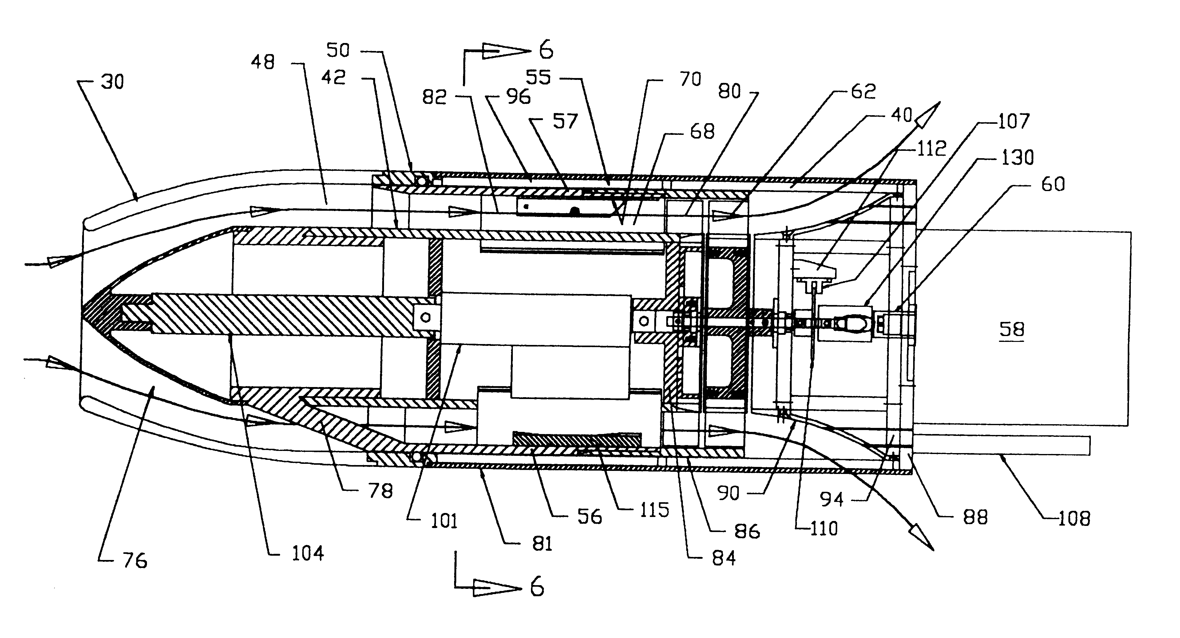
In response to a signal from a turbine speed sensor, an electronic controller activates an electromechanical or electro-hydraulic actuator to move the centerbody / forward valve tube. The centerbody / forward valve tube is moved toward position 2 when flight conditions and generator load cause the turbine to overspeed above a certain tolerance. The centerbody / forward valve tube is moved toward position 1 when flight conditions and generator load cause the turbine speed to fall below a predetermined speed, within a certain tolerance, thereby tending to maintain the turbine wheel and generator speed within a predetermined speed range.
Thus, in a full power extraction mode, under changing flight conditions with varying air density and flight velocity, only sufficient air flow with sufficient kinetic energy will be admitted into the variable area diffuser and through the variable area nozzle to the turbine to maintain close to constant fluid dynamic power in the airflow through the turbine. Thereby the turbine and generator speeds are maintained at their design values. The variable area nozzles working in conjunction with the variable area inlet, control the variation in the airflow velocity to the stator and turbine to cause the turbine to efficiently extract energy from the air stream throughout the moderate subsonic through supersonic flight speed regime. The combination of admitting only the airflow required, and of efficiently extracting energy throughout the intended range of flight operation, minimizes drag throughout the operating flight speed range. During portions of a flight, when power requirements are reduced below normal operating levels, or completely cease, the centerbody / valve tube is advanced partially or completely forward toward a third or closed position (position 3), further reducing or completely closing off the inlet air flow, and further closing the nozzles, thereby presenting a clean aerodynamic forebody, which further reduces drag in the reduced or ceased power operating modes.
Advantageous applications of the present invention include use with aircraft external electronic pods while flying at moderate to high subsonic through supersonic speeds. The aircraft will benefit by way of increased aircraft speed and / or range from reduced drag both while extracting power from the air stream and during the non-operating mode. The air turbine of the present invention results in a smaller maximum external diameter than present external bladed systems for a given level of power extracted. The ram air turbine of the present invention may be used in external aircraft stores or pods for generating auxiliary or emergency power to be supplied to the aircraft as needed. The present invention is applicable to both manned and unmanned aircraft. Where cooling capability is advantageous or required the embodiment of the present invention with cooling capability offers size and weight advantages over present systems which require separate cooling systems when an external bladed ram air turbine is used for power generation.

Problems solved by technology

However as the flight speed of the aircraft increases, to values where the relative velocity between the air and blade becomes sonic, efficiencies of the process fall off dramatically.
In these regimes the shock waves, induced by the blades, create high frontal pressures on the blades and flow separation over and behind the blades, with corresponding dramatic increases in drag.
With increasing power needs for electronic systems in external aircraft pods, this drag penalty for the external turbine bladed technology has increasing undesirable impact on aircraft performance, adversely affecting speed, maneuverability and range.
In addition, external bladed ram turbine generators do not have the capability to provide direct cooling from the exhaust air.
In applications where portions of the flight profile include high speed flight which induces significant aerodynamic heating on the skin of a pod, additional active cooling systems are required for the pod electronics, entailing additional size and weight penalties.
During supersonic flight of the missile, the shock waves off the front of the missile increase the pressure in front of the exhausts, tending to increasingly throttle the flow through the ducts and turbine as the missile accelerates, thereby tending to limit the maximum speed of rotation of the turbine.
However, drag reduction features were not a goal and were not present.
No direct cooling capability is provided.
However, the basic approach offered, including the air induction and then venting, with the shape of the leading edge of the door diverting the flow outward through vents, inherently does not offer a reduced drag.
As in the Boulton, et al, patent, the process of admitting, bypassing, and then exhausting airflow presents drag penalties due to the momentum interchange.

Method used


Image

  • Low drag ducted Ram air turbine generator and cooling system
  • Low drag ducted Ram air turbine generator and cooling system
  • Low drag ducted Ram air turbine generator and cooling system

Examples


first embodiment

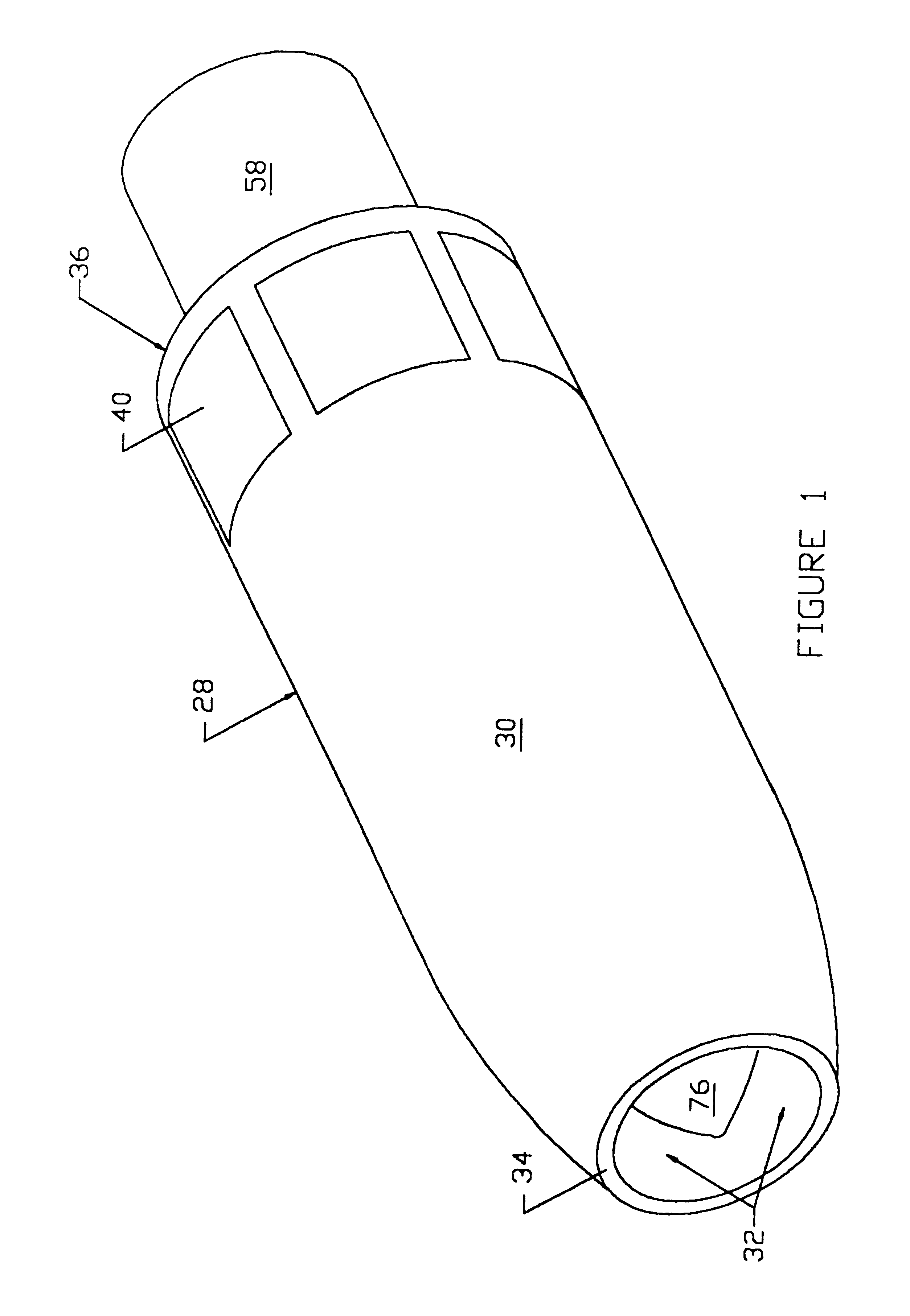
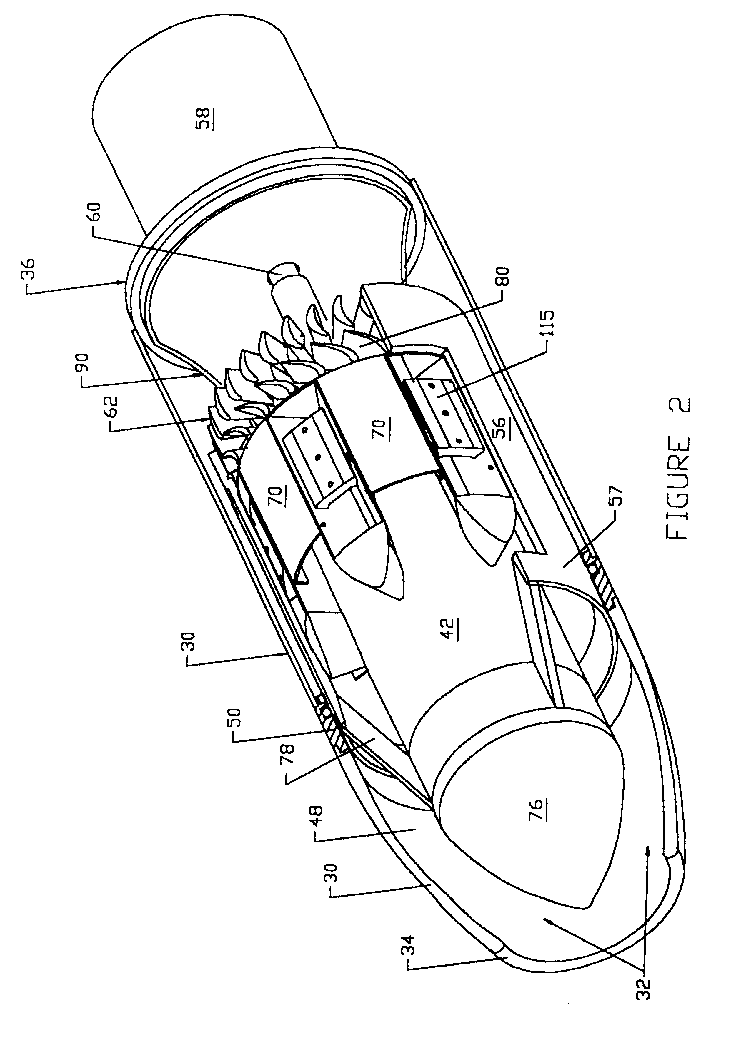
Referring initially to FIGS. 1-4, the overall construction of the ram air turbine generating device 28 in accordance with this invention will be described. The device 28 comprises a generally cylindrical external fairing 30 extending between an inlet passage or diffuser 32 at leading end 34 and an aft end 36, and having a plurality of exhaust ports 40 proximate the aft end. The external fairing 30 is mounted to a primary structure consisting of a plurality of axially spaced circumferential rings 50 located in the front section of the device 28, and a plurality of axially spaced bulkheads located in the aft section of the device 28, that are connected by a plurality of longitudinal spars 96. A centerbody / valve tube 57 is slidably supported in axial slots 97, best shown in FIGS. 6 and 6a, composed of linear ball bearing or other suitable slide mechanisms which are positioned in the inner surface of the longitudinal spars 96 and which in turn are mated with matching axial slide members...

second embodiment

the nozzle and nozzle control mechanism is shown in FIGS. 12, 13, 14a, 14b, 15a, and 15b. This embodiment utilizes an annular nozzle 272 including interleaved panels. The annular nozzle operates by contracting uniformly around center flow guide 42 to restrict flow between through the space between annular nozzle 272 and center flow guide 42. Referring first to FIG. 12 and FIGS. 14a and 14b. A plurality of active interleaved nozzle control panels 270 and 271 are connected to each other at their forward and aft ends by bushings 275, which are flanged at each end. One flange of each bushing 275 is secured to the radially inner surface of the radially inner primary panels 270. The shafts of the bushings protrude through slotted holes 276 in the secondary panels 271, with the other flanges of the bushings being on the radially outer side of the secondary panels 271. The flanged bushings 275 hold the primary and secondary panels within a predetermined distance of each other while the prim...


PUM


Abstract

A low drag ducted ram air turbine generator and cooling system is provided. The ducted ram air turbine generator and cooling system has reduced drag while extracting dynamic energy from the air stream during the complete range of intended flight operating regimes. A centerbody / valve tube having an aerodynamically shaped nose is slidably received in a fairing and primary structure to provide a variable inlet area. An internal nozzle control mechanism attached to the valve tube positions nozzle control doors to provide variable area nozzles directing air flow to the turbine stator and rotor blades to maintain optimum generator efficiency. An alternate embodiment includes an annular internal nozzle having interleaved panels to modulate the air flow to the turbine.

Description

1. Field of the InventionThe present invention relates generally to ram air turbine devices and more particularly to a ducted type ram air turbine generator.2. Description of the Prior ArtOne type of ram air turbine generator disclosed in the prior art consists of a ram turbine generator with the blades mounted externally to extract power from an air stream. The blades are usually mounted to a rotatable housing forming part of a center aerobody with the turbine center shaft drivingly coupled to an electric generator, or a hydraulic pump, or both if desired. Turbine speed control and power output are maintained through speed control mechanisms which vary the pitch of the blades under varying flight conditions, thereby tending to maintain constant power to the blades from the air stream. This type of ram air turbine generator is presently the predominate type used on externally carried electronic pods, primarily in military applications, and for emergency power electric / and or hydraul...

Claims


Application Information

Patent Timeline
IPC IPC(8): F01D17/06F01D15/00F01D25/08F01D17/14F01D25/12F01D15/10F01D17/00F02C7/04F02C7/042
CPCB64D41/007F01D15/10F01D17/06F01D17/14F02C7/042F01D25/12F05D2220/34Y02T50/671Y02T50/675Y10T137/0536Y10T137/0645Y02T50/60B64D33/08
Inventor GHETZLER, RICHARDWOJTALIK, JR., JEROME F.KRUSE, NEILSSTEPHENS, KENDAL R.SCHMULENSON, HAROLD
Owner GHETZLER AERO POWER CORP
Learn More