Intermediate electrical connector

a technology of electrical connectors and connectors, applied in the direction of connection contact member materials, pulse techniques, coupling device connections, etc., can solve the problems of poor contact poor contact, and insufficient elastic deformation of the conductive member of the electrical connector

Inactive Publication Date: 2001-08-28
HIROSE ELECTRIC GROUP
View PDF5 Cites 39 Cited by
  • Summary
  • Abstract
  • Description
  • Claims
  • Application Information

AI Technical Summary

Benefits of technology

It is another object of the invention to provide an intermediate electrical connector with the conductive member capable of providing a large amount of deformation and stable contact and low electrical resistance without applying a high pressure.
It is still another object of the invention to provide an intermediate connector and an electrical connection system capable of providing a large amount of replacement without applying high pressure on the conductive elastomer, thereby providing good contact without increase in electrical resistance.
Since the outside diameter of the shoulder portions is smaller than the inside diameter of the support aperture, the elastic deformation of the protruded section is larger than that of the retention section; that is, the conductive member is deformed to a large extent regardless of the retention section. Thus, the circuit portions of two connection objects are short-circuited via the conductive member. The large amount of deformation in the conductive member makes the contact stable and the electrical resistance low.
The conductive member is held by the edges of aperture or a bridge extending across an aperture provided in the support plate. In the latter case, the conductive member may made asymmetric to tilt, thereby increasing the amount of movement.
According to still another aspect of the invention, at least one of the contact faces has at least first and second contact sections which make successive contacts with one of the circuit portions of the connection objects. When it receives contact pressures between connection objects, the conductive member are elastically compressed and short-circuit the circuit portions of the connection objects. When compressed, the conductive member decreases in electrical resistance at the initial stage but increases beyond the initial stage. According to the invention, when the amount of compression increases, the second contact section makes contact to increase the entire contact area thereby reducing the electrical resistance. Thus, the electrical resistance is kept low for large amounts of compression. In addition, the initial contact area is so small that the compression force is small.

Problems solved by technology

However, the above conventional intermediate electrical connector provides no satisfactory amount of elastic deformation of the conductive member 52.
Moreover, when the intermediate electrical connector receives an external force, the circuit boards momentarily moves in the compression direction of the conductive member, causing poor contact of the conductive member.
However, the above conventional connector provides no satisfactory amount of deformation, thus causing poor contact.
However, the amount of elastic deformation is so small that the contact resistance is high.
In addition, if this high compression is applied to a number of conductive members, the combined force applied to the mating circuit boards is disadvantageously high.
Moreover, when the intermediate electrical connector receives an external force, the circuit boards are moved in the compression direction of the conductive member, causing poor contact of the conductive member.
However, too much elasticity causes lower electrical characteristics described above.

Method used


Image

  • Intermediate electrical connector
  • Intermediate electrical connector
  • Intermediate electrical connector

Examples


Embodiment Construction

Embodiments of the invention will now be described with reference to FIGS. 3-28.

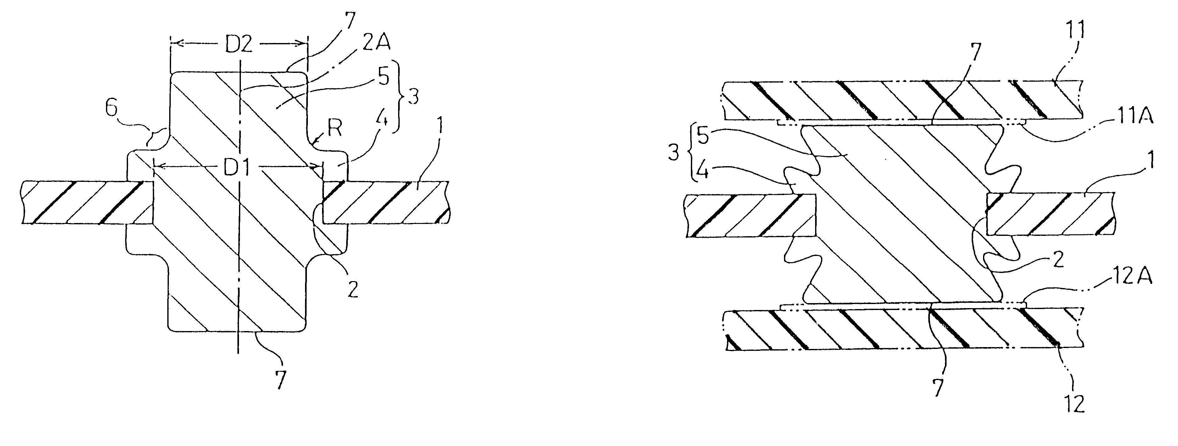
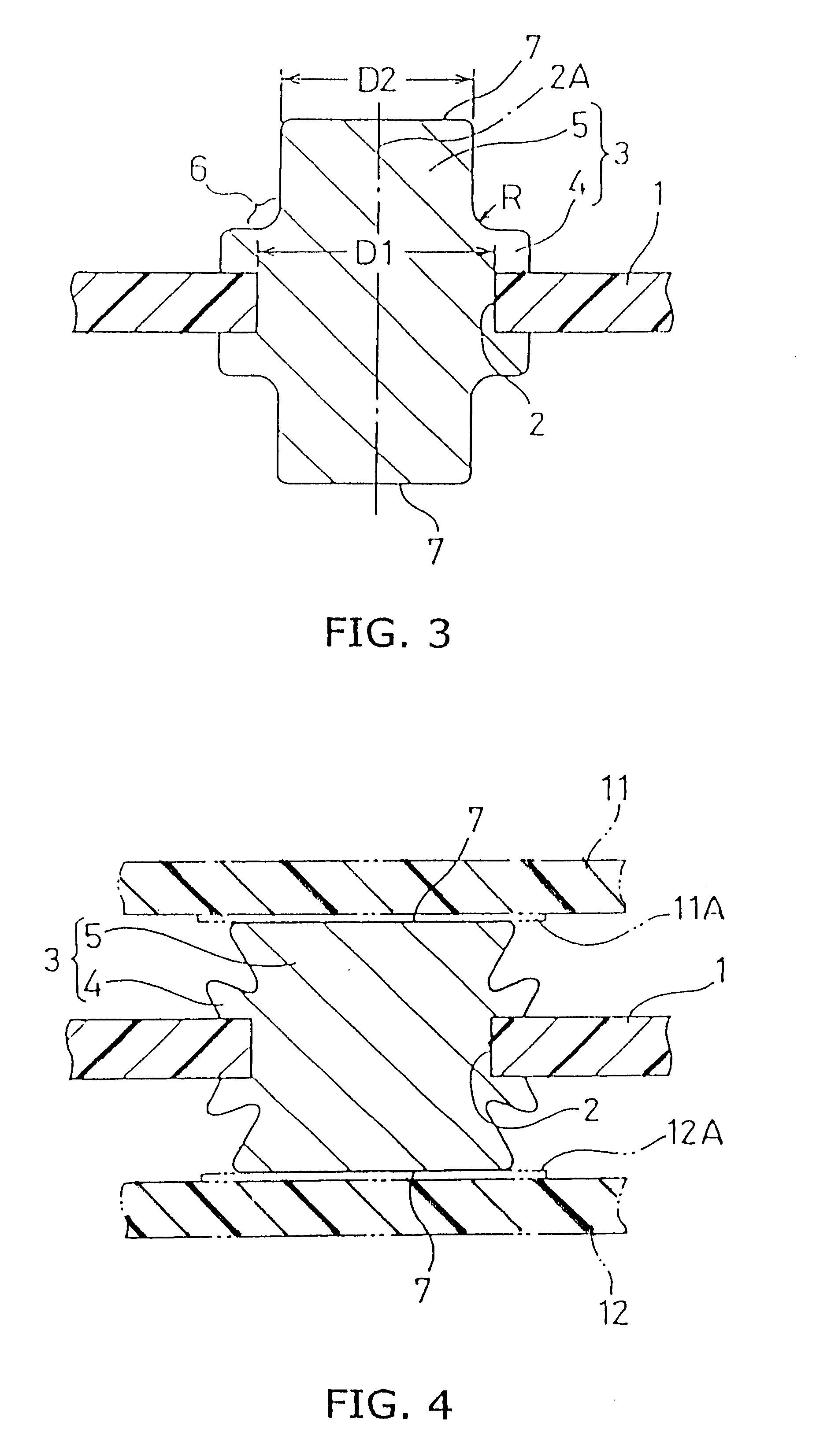
In FIG. 3, a support plate 1 is made of dielectric material. A plurality of support apertures 2 having an inside diameter D1 are provided in the support plate 1, and a plurality of conductive members 3 are attached thereto by integral molding such that each conductive member 3 is held by the circumferential edges of each support aperture 2. Preferred examples of the dielectric material include films of polyimide, polyester, and polyamide.

The conductive member 3 is made by mixing an elastic polymeric material with a conductive powder or particles. Preferred examples of the elastic polymers are silicone rubber, polybutadiene rubber, natural rubber, polyisoprene, styrene-butadiene copolymer rubber, acrylonitrile-butadiene copolymer rubber, ethylene-propylene copolymer rubber, urethane rubber, polyester rubbers, chloroprene rubber, epichlorohydrin rubber, and soft liquid epoxy rubber. Examples of the conduct...


PUM


Abstract

An intermediate electrical connector comprises a support plate (1) which is made of a dielectric material and has at least one support aperture (2) having an inside diameter; and at least one conductive member (3) provided through the support aperture to short-circuit circuit portions of connection objects. The conductive member is made of a conductive elastomer and comprises a retention section (4) with flange portions for engage with the support aperture to attach the conductive member to the support plate; and an elastic protruded section (5). The elastic protruded section extends from the retention section in a direction of thickness of the support plate to form at opposite ends contact faces (7) for elastic contact with the circuit portions (11A, 12A) of the connection objects (11, 12) and has, adjacent to the retention section, shoulder (6) portions having an outside diameter which is smaller than the inside diameter of the support aperture.

Description

1. Field of the InventionThe present invention relates to intermediate electrical connectors.2. Related ArtAn intermediate electrical connector is used to connect two circuit broads or corresponding circuit portions of connection objects. The intermediate electrical connector comprises a support plate of dielectric material and a conductive member extending through the support member. The conductive member is a molding of a conductive elastomer or a mixture of elastic polymeric material and conductive powder.FIG. 1 shows an example which comprises a support member 51 of dielectric material and a conductive member 52 with upper and lower conic surfaces 52A attached thereto by integral molding. The upper and lower flat end faces 53 and 54 make elastic contact with the circuit portions of connection objects. The number of conductive members 52 provided on the support member 51 corresponds to the number of circuit portions of the connection objects.In FIG. 2, two connection objects or c...

Claims


Application Information

Patent Timeline
Patent Type & Authority Patents(United States)
IPC IPC(8): H01R13/24H01R13/22H05K3/32H05K3/36H05K1/11H01R12/71
CPCH01R13/2414H03K2217/96076H01R12/714H05K3/325H05K3/368H05K1/11
Inventor SAKATA, TSUYOSHINAGAWATARI, TAKASHI
Owner HIROSE ELECTRIC GROUP
Why Eureka
Try Eureka