Optical beam deflector modifying phases of respective portions of optical beam by two arrays of optical phase modulators

a technology of optical phase modulator and optical beam, which is applied in the direction of instruments, semiconductor lasers, lenses, etc., can solve the problems of deteriorating light beam quality, loss of laser beam energy of portions of laser beam which are diffracted in directions other than the desired direction of deflection, and impaired performance of apparatuses utilizing optical beam deflectors

Inactive Publication Date: 2002-01-22
FUJIFILM HLDG CORP +1
View PDF1 Cites 38 Cited by
  • Summary
  • Abstract
  • Description
  • Claims
  • Application Information

AI Technical Summary

Problems solved by technology

However, these techniques have the following drawbacks.
Luminous energy of portions of the laser beam which are diffracted in directions other than the desired direction of deflection is lost, quality of the light beam is deteriorated, and performance of apparatuses utilizing the optical beam deflector is impaired.
(ii) Since the deflection is realized by mechanical displacement of the microlens array, it is not possible to perform agile, stable, and reliable scanning by using the above optical beam deflectors.
However, due to use of only one array of optical phase modulators, this technique has the following drawbacks.
(i) Dead spots or stripe-shaped electrode areas of the array of optical phase modulators cause loss of luminous energy, and deform the wavefront of an output laser beam.
However, when the pitch of the electrodes is decreased, a considerable amount o

Method used


Image

  • Optical beam deflector modifying phases of respective portions of optical beam by two arrays of optical phase modulators
  • Optical beam deflector modifying phases of respective portions of optical beam by two arrays of optical phase modulators
  • Optical beam deflector modifying phases of respective portions of optical beam by two arrays of optical phase modulators

Examples


first embodiment

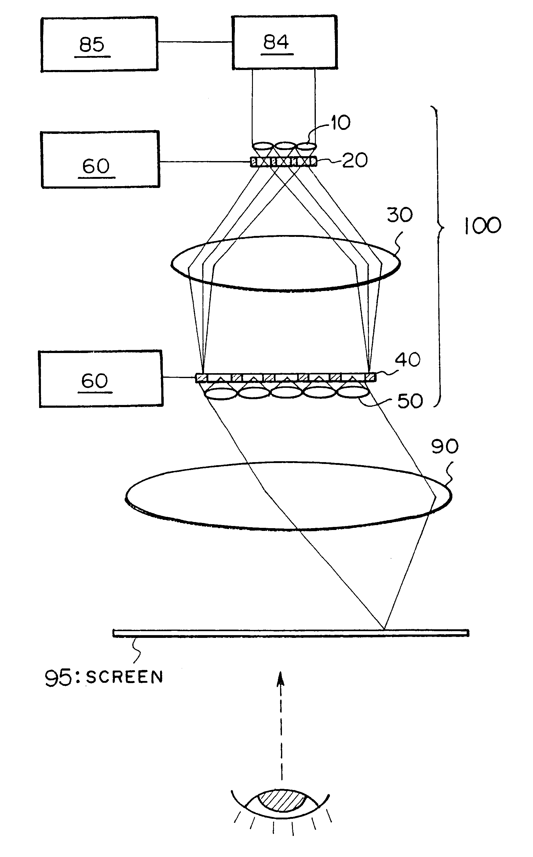
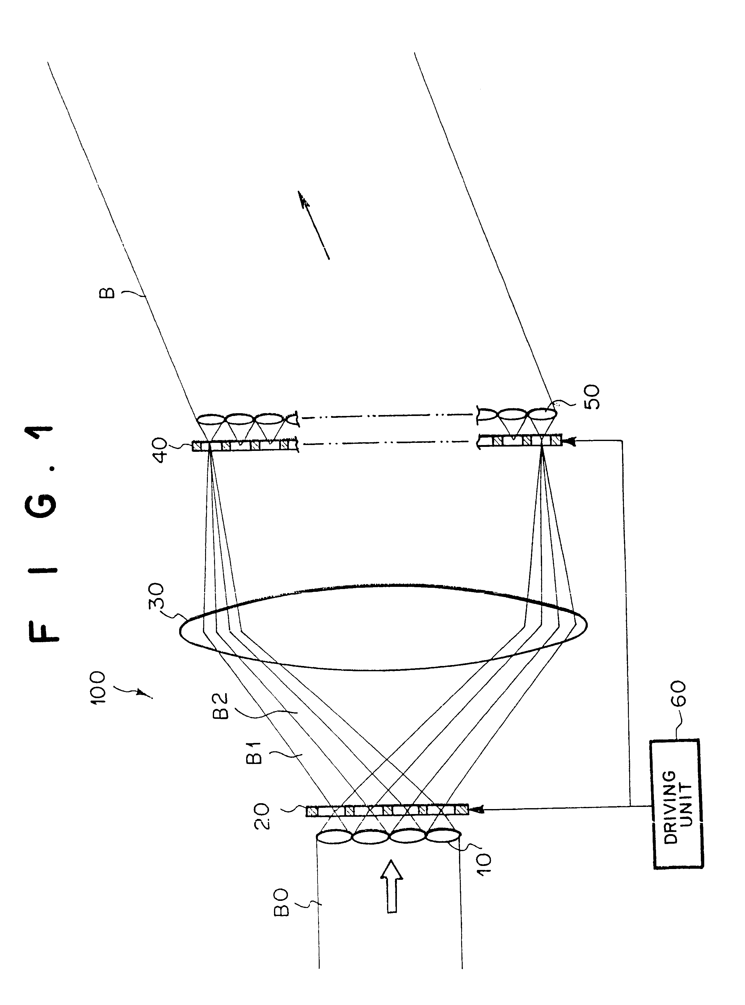
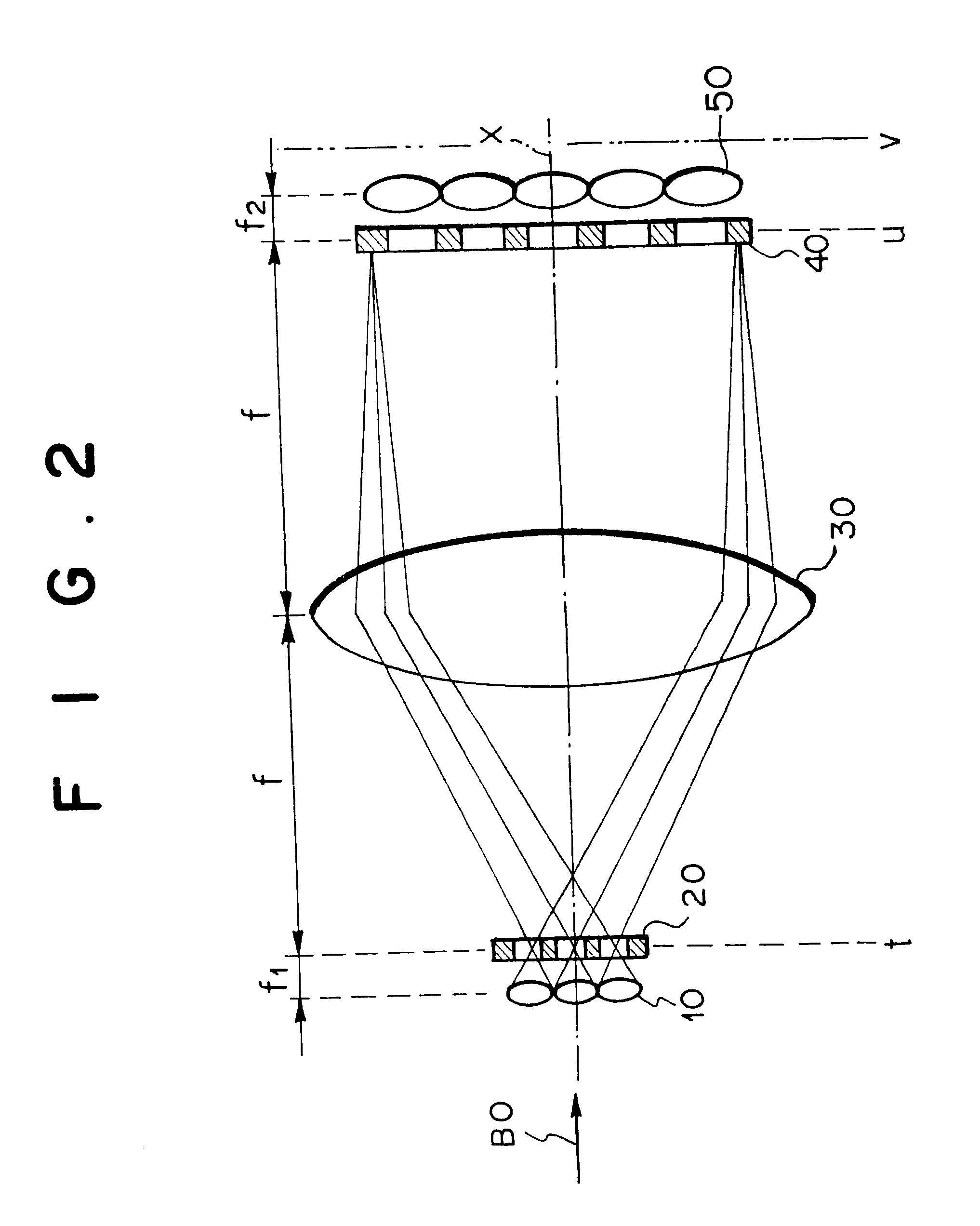
FIG. 1 is a side view illustrating the construction of the optical beam deflector as the first embodiment of the present invention. The optical beam deflector of FIG. 1 contains a lens array 10, a first optical phase modulator array 20, a Fourier transform lens 30, a second optical phase modulator array 40, a Fourier transform lens array 50, and a driving unit 60.

The lens array 10 is an array of a plurality of lenses, and collects a first plurality of portions (micro crosssections) of an incident laser beam B0 into a plurality of spots, respectively. Although only four lenses are indicated in the vertical direction in FIG. 1 for the sake of simplicity, in practice, a great number of lenses are arranged in the lens array 10. The first optical phase modulator array 20 is an array of optical phase modulators corresponding to the plurality of lenses in the lens array 10. The optical phase modulators in the first optical phase modulator array 20 separately modulate, at the plurality of s...

second embodiment

FIG. 5 is a diagram illustrating the construction of the optical beam deflector as the second embodiment of the present invention.

The optical beam deflector 100' of FIG. 5 is different from the optical beam deflector 100 of FIG. 1, in that the optical beam deflector 100' of FIG. 5 does not contain the Fourier transform lens 30, and contains a second (image-forming) lens array 50' instead of the Fourier transform lens array 50 in FIG. 1.

In the optical beam deflector 100' as the second embodiment, Fourier transformation is not performed. Instead, the first lens array 10 forms, on the back focal planes of the lenses of the first lens array 10, a plurality of spots from the plurality of portions of the laser beam B0, and images of the plurality of spots are further formed by each lens in the second lens array 50'. The first and second optical phase modulator arrays 20 and 40 are driven by the driving unit 60 to modulate the phases of the respective portions of the laser beam in a simila...


PUM


Abstract

An optical beam deflector in which a crosssection of an incident optical (e.g., laser) beam is divided into a first plurality of portions (micro crosssections) by an array of first lenses, a plurality of phases of the optical beam in the first micro crosssections are respectively modified by an array of first optical phase modulators so that a desired phase distribution is realized over the crosssection of the optical beam, and thereafter the crosssection of the optical beam is further divided into a plurality of second micro crosssections, and a plurality of phases of the optical beam in the second micro crosssections are respectively modified by an array of second optical phase modulators. An array of second lenses is provided corresponding to the second optical phase modulators to collect a plurality of portions of the optical beam output from the second optical phase modulators. The first and second optical phase modulators are driven by a driving unit so that the optical beam output from the array of second lenses as a whole is finally directed in a desired direction of deflection or to a desired point.

Description

1. Field of the InventionThe present invention relates to an optical beam deflector. The optical beam deflector can be used, for example, for generating a scanning beam in a laser beam scanning apparatus, and the laser beam scanning device can be used in recording, reading, and displaying information, laser radar, intersatellite communication, and the like.2. Description of the Related ArtConventionally, the following techniques are proposed for optical beam deflectors:(1) Laser Beam Deflectors Using Microlens Array(a) W. Goltsos, and M. Holz, "Agile Beam Steering Using Binary Optics Microlens Arrays," Optical Engineering, vol. 29 (1990), 1392.(b) T. D. Milster and J. N. Wong, "Modeling and Measurement of Micro-Optic Beam Deflector," in "Design, Modeling, and Control of Laser Beam Optics," SPIE Proceedings, vol. 1625 (1992), 78-83.In the techniques disclosed in the above references (a) and (b), two microlens arrays are provided in a telescope arrangement, and an incident laser beam ...

Claims


Application Information

Patent Timeline
IPC IPC(8): G02B3/00G02F1/29H01S5/40H01S3/101H01S5/00
CPCG02B27/0961G02F1/292H01S5/4025H01S3/101H01S5/005
Inventor HIIRO, HIROYUKI
Owner FUJIFILM HLDG CORP
Why Eureka
Try Eureka