Laser imaging system with progressive multi-beam scan architecture

a multi-beam scan and scanning technology, applied in the direction of color television details, instrumentation, picture signal generators, etc., can solve the problems of widespread application of high-resolution video projectors, lack of suitable display systems, and severely limited video images seen by viewers

Inactive Publication Date: 2002-02-26
PHOTERA TECH
View PDF46 Cites 79 Cited by
  • Summary
  • Abstract
  • Description
  • Claims
  • Application Information

AI Technical Summary

Benefits of technology

In a system described herein a polygon scanner scans at least two modulated laser beams horizontally and a galvanometer (galvo) mirror scans the beams vertically. The beam spots (the "incident locations") on the polygon scanner are arranged in a row aligned with the perimeter of the polygon. The beams in the row are arranged in pairs, and typically only one beam from each pair will be scanning at any one time. In such an embodiment, where the duty cycle is slightly less than 50%, the laser illumination can be switched between two interleaved beam scans, thereby allowing a single modulator to be used for both beams, which can provide significant cost advantages and improve system efficiency without requiring a long polygon facet. Additional pairs of beams can be added as described herein to improve resolution and / or increase pixel count without requiring a high-speed polygon scanner or a highly-linear galvo scanner. For example, increasing the number of pairs from one to two can be used to double the resolution or to provide a two-fold reduction in polygon rotational speed. Accordingly, a low-cost polygon scanning mirror, with a small diameter and a small facet length well within the limits of available technology, can be utilized. For example, the height of each facet need be only one beam diameter and its length need only be two beam diameters, which provides significant cost advantages.
In other embodiments a single light modulator is used to modulate the primary laser beam, and an optical switch is used to switch the modulated beam between the first and the second optical paths to provide the first and second laser beams. Particularly, the primary laser beam is modulated by the modulator during a first time interval and scanned to display a first image line, then switched from the first optical path to the second optical path, then modulated during the second time interval and scanned to display the second image line, and then switched from the second optical path to the first optical path after the second time interval to repeat the operations for all lines in the image. Advantageously, such an arrangement reduces by a factor of two the number of high-cost modulators required at the cost of an additional switch. Furthermore, such a system efficiently uses the energy of the primary laser beam.
The progressive scanning system easily can be expanded by addition of one or more pairs of beams that progressively scan the image in concert with the first pair. Generally, additional pairs are added so that the total number of pairs is a power of two; i.e. one pair, two pairs, four pair, eight pairs, and so forth. The spatial separation between the two beams in each additional pair is approximately equal to the spatial separation of the first pair. The first beam of each succeeding pair typically is situated midway between the first and second beams of another pair, and the propagation angle between each adjacent beam is approximately equal, while lying substantially within a single plane. For example, a second pair is arranged with the first pair in a row in which the first beam of the second pair is situated midway between the first and second beams of the first pair. Each incident location is separated by an approximately equal distance from the adjacent incident locations. Furthermore, the propagation of the four beams are non-parallel to each other, having propagation angles between adjacent beams that is approximately uniform, although the four beam paths may lie in a single plane (substantially uniplanar but non-parallel within that plane). In an example with four pairs, a third and fourth pair are arranged so that the first beam of the third pair is situated between the first beams of the first and second pair, and the first beam of the fourth pair is situated between the first beam of the second pair and the second beam of the first pair.
In some embodiments, a full-color image can be displayed by the progressive scanning system described herein. For full-color images, each of the beams described can incorporate separate red, green and blue (RGB) components which are individually modulated by separate red, green, and blue modulators. In one such embodiment, the first modulated laser beam comprises a first RGB combined laser beam, and the second modulated laser beam comprises a second RGB combined laser beam that are progressively scanned as described herein. Additional RGB beams can be added as described herein to increase resolution and / or reduce polygon rotational speed.

Problems solved by technology

However, the quality of the video images seen by a viewer is severely limited by the systems that project the image on a screen.
The lack of suitable display systems has been a significant factor in preventing widespread application of high resolution video projectors.
Generally, the available projection display systems are either very expensive, or they do not provide a high quality image at high frame rates and high resolution, and with sufficient brightness.
However, as resolution and brightness requirements increase, CRT-based projectors reach some physical limits and therefore, other ways to project video and computer information have been proposed and developed.
However, non-scanning systems have demanding electronics requirements due to the large number of pixels that must be accessed simultaneously, and the available modulators are difficult and expensive to scale up to such sizes.
Unfortunately, in the context of large high resolution displays, the available two-dimensional modulators have a limited pixel count.
Furthermore, the brightness of the projected display in constant illumination systems is low at higher pixel counts because the fractional area of the pixels decreases at higher densities, thereby reducing light output.
The design issues associated with such constant illumination systems are difficult and complex, and in many cases they directly limit the achievable results.
However, a practical system for scanning an electron beam is very different from a practical system for scanning a modulated laser beam.
Laser scanning configurations have practical hardware limitations on the modulation rate and the scanning rate.
Particularly, the available light modulators are limited in bandwidth.
Further bandwidth limitations are imposed by the scanner and scanning configuration.
Although some high bandwidth polygon scanners are available, they are very expensive and impractical.
Galvo mirrors are much less expensive, but they have much smaller bandwidth, and are plagued with nonlinearities.
For example, a pushbroom system for a 1000 line image requires 1000 laser beams, which reduces the bandwidth requirements of the modulators at the cost of a need for additional modulators.
A significant challenge in implementing laser scanning systems relates to achieving a clear, high quality image with high resolution while avoiding psycho-visual artifacts of laser scanning such as latency, image doubling, and image breakup.
One problem with laser scanning systems relates to the differential in refresh time between adjacent or neighboring pixels.
However, the laser-based vernier scan architecture discussed previously suffers from severe artifacts relating to the large differential refresh time between neighboring pixels.
Unfortunately, implementation of the paintbrush architecture poses severe problems.
First, it has proven very difficult to balance the relative brightness of closely-positioned beams in a manner consistent with the elimination of horizontal banding.
Such an extremely precise scanning mechanism is not presently available.
Unfortunately, implementation of the pushbroom approach requires linear array modulators with thousands of individual elements, none of which are commercially available at the present time.
Furthermore, the closely-spaced beams pose the same problem as in the paintbrush approach; particularly it is very difficult to balance the relative brightness between lines, thereby eliminating horizontal banding.
Although it may be desirable that the beam have an approximately uniform intensity across its diameter that drops to zero intensity at its boundaries, practical laser beams typically do not have such an ideal configuration.
If writing the first beam were to begin in such a position, the first beam would be divided and reflected in two different direction directions, which is an undesirable result for this arrangement.

Method used


Image

  • Laser imaging system with progressive multi-beam scan architecture
  • Laser imaging system with progressive multi-beam scan architecture
  • Laser imaging system with progressive multi-beam scan architecture

Examples


Embodiment Construction

of a High Resolution Display

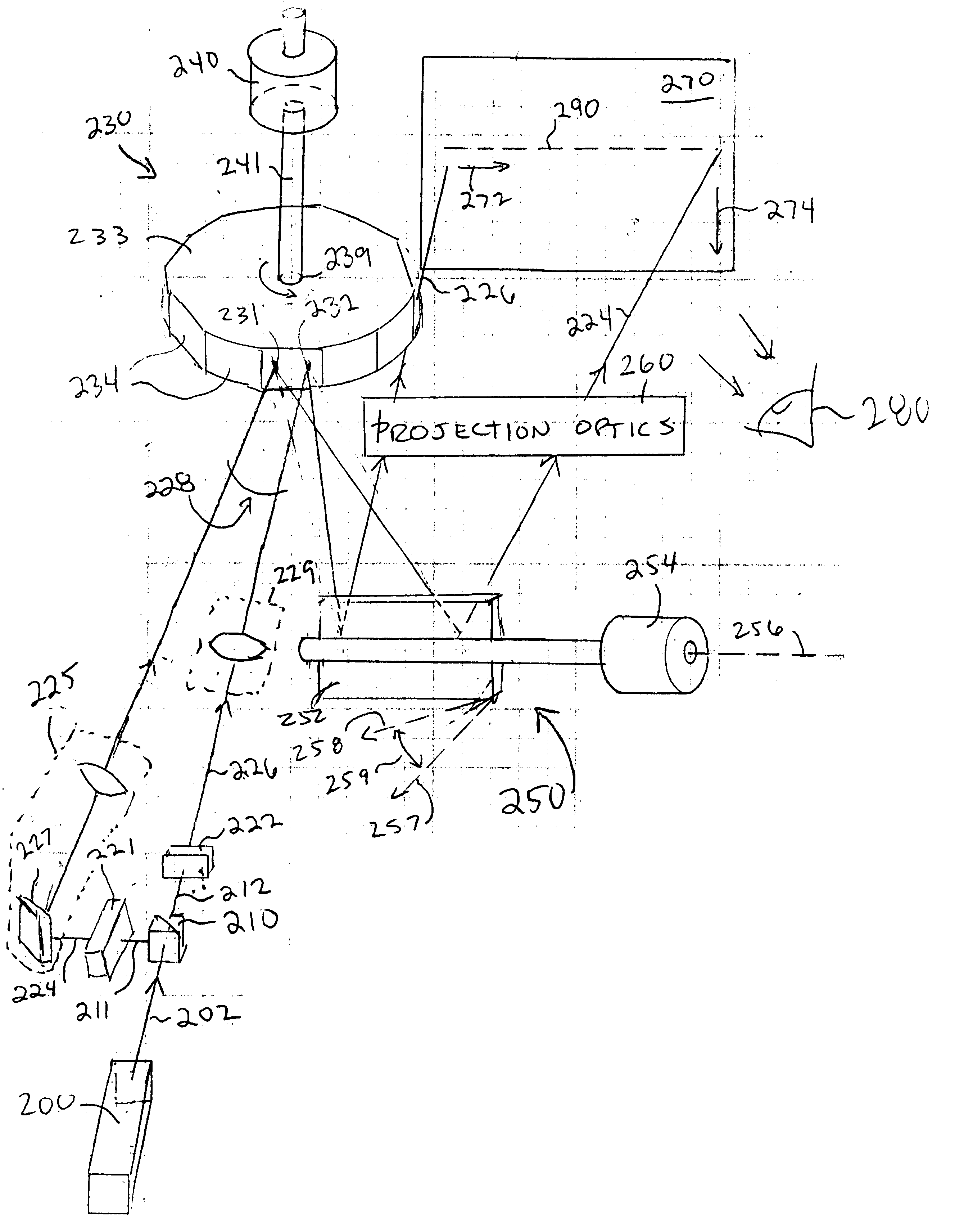
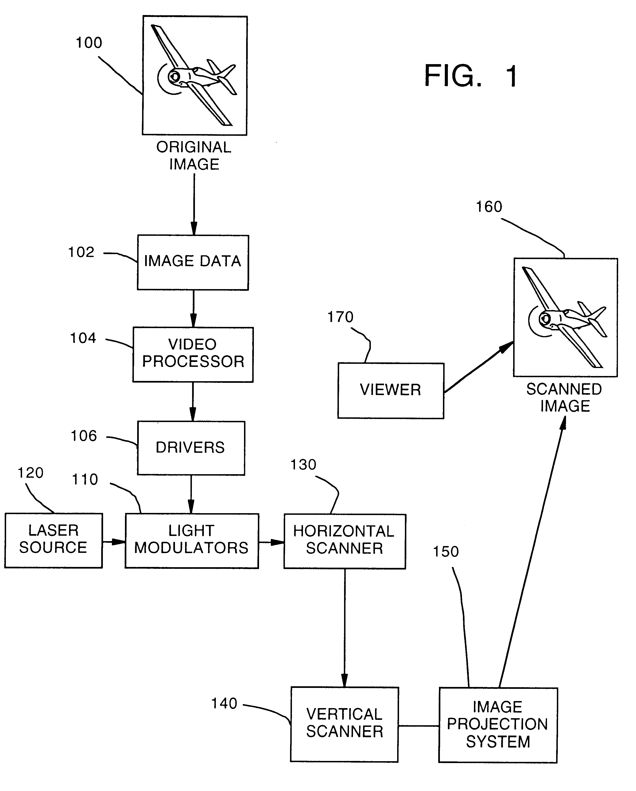
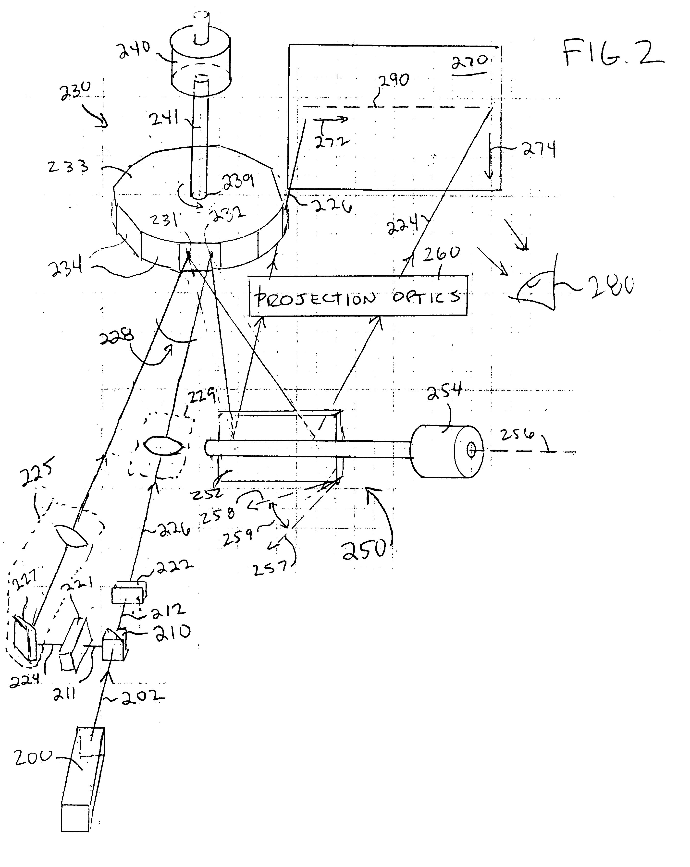
The invention described herein can be implemented in many different configurations. One particular example is a 2000.times.1000 pixel display in which each pixel must be refreshed at a 60 Hz rate. During the course of each frame, 1000 sequential lines are written progressively, each line being modulated to generate 2000 resolvable pixels. Neglecting the need for flyback and retrace intervals for the purpose of illustration, this rate of line initiation requires that a new line be commenced every 16.7 microseconds. It is of note that such a system requires a video bandwidth approximately twice that of interlaced HDTV (1920.times.1080).

For purposes of comparison, using a single-beam to generate 2000 pixels within a 16.7 microsecond time interval theoretically requires a modulation bandwidth of 120 MHz. However, when a polygon mirror / galvanometer is used to generate the horizontal / vertical scan format, the practical limitations imposed both upon polygon scan...


PUM


Abstract

A progressive scan architecture for displaying a two-dimensional image by alternately scanning two or more laser beams, one after the other with a time delay between adjacent beams. The beams are arranged to become incident upon a polygon scanner in a row with an approximately uniform spatial separation and an approximately equal angle between adjacent beams. The polygon scanner scans horizontally and a galvanometer-driven mirror scans vertically. Adjacent lines are progressively scanned in sequence from top to bottom, which advantageously reduces or eliminates psycho-visual effects and is tolerant of non-linearities in the vertical scanner, allowing use of a low-cost galvo mirror. Typically, the beams in the row are arranged in pairs, and only one beam from each pair will be scanning at any one time. Embodiments are described in which the duty cycle is slightly less than 50% and the laser illumination is switched between two interleaved beam scans thereby allowing a single modulator to be used for both beams which provides significant cost advantages and improves system efficiency. For full-color images, each of the beams described can incorporate separate red, green and blue (RGB) components which are individually modulated by separate red, green, and blue modulators. The system can be scaled up with one or more additional pairs of beams to improve resolution and / or increase pixel count without requiring a high-speed polygon scanner or a highly-linear galvo scanner. Furthermore, the height of each facet in the polygon mirror need be only one beam diameter and its length need only be two beam diameters, which allows the system to approach the minimum pixel size attainable, which is useful to provide high efficiency and high brightness in the image.

Description

1. Field of the InventionThe present invention generally relates to scanning projection and display systems. More particularly, it relates to projection and display systems that scan one or more modulated laser beams to generate an image.2. Description of Related ArtRapid advances in information processing and video production have made it technically possible to provide high resolution video images. However, the quality of the video images seen by a viewer is severely limited by the systems that project the image on a screen. The lack of suitable display systems has been a significant factor in preventing widespread application of high resolution video projectors. Generally, the available projection display systems are either very expensive, or they do not provide a high quality image at high frame rates and high resolution, and with sufficient brightness. If available at an affordable cost, high resolution projection displays would have widespread and diverse uses such as projecti...

Claims


Application Information

Patent Timeline
Patent Type & Authority Patents(United States)
IPC IPC(8): G02B26/12H04N9/31
CPCH04N9/3129G02B26/123
Inventor FLINT, GRAHAM W.
Owner PHOTERA TECH
Why Eureka
Try Eureka