High data rate smart sensor technology

a sensor and data rate technology, applied in the field of high data rate smart sensor technology, can solve the problems limited frame rate or count rate, and inability to solve the problem of large detector-array technology,

Inactive Publication Date: 2002-03-26
CONTINENTAL ADVANCED LIDAR SOLUTIONS US LLC
View PDF4 Cites 119 Cited by
  • Summary
  • Abstract
  • Description
  • Claims
  • Application Information

AI Technical Summary

Benefits of technology

It is the object of the present invention to provide high-speed devices for the collection and analysis of photon or particle, image or counting data which overcomes problems of prior systems associated with data bottlenecks, slow image processing and slow counting.
It is still further the object of the present invention to provide a device for high-speed implementation of data processing algorithms on analog data and for outputting only the important data.

Problems solved by technology

Current large detector-array technologies, for particle or photon imaging or for counting, are frame rate or count rate limited.
The imaging speed limitation is usually related to the need to digitize all the data in the array and transfer it to a digital computer for processing.
Digitizing and transferring all the data produces a data rate bottleneck and digitally processing all the data produces a processing rate bottleneck.
However, because of the shortcomings of these systems, namely high cost, large size and large-power consumption, this solution is not in common use.
Since the camera or sensor is only composed of a few chips it is very compact and consumes little power.
There is currently a very complex analog processing architecture, using mammalian retina circuit analogs that propose to solve the high-data-rate, image-processing problem.
The shortcomings of z-plane technology are: (1) it requires a large volume of silicon and hence is expensive (512 chips for a 512.times.512 detector array for example); (2) the z-plane chips must thinned by a special process and all interconnected; this is expensive and difficult to accomplish without error; (3) image resolution is limited by the thickness of the z-plane chips; (4) difficulties dissipating heat in the z-plane three-dimensional cube limits processing speed; and (5) the number of outputs are very large, equal or greater than the number of detectors.
Limitations of the biological-analogy algorithm are: (1) spatial averaging reduces resolution to larger than the pixel size; (2) difficulties with implementing gain and offset corrections leads to spurious images and noise; and (3) the silicon-retina edge algorithm is of limited application.
Data collection is particularly limited in structural biology investigations of dilute samples where detectors have not kept pace with synchrotron source development.
The Extended X-ray Absorption Fine Structure (EXAFS) technique, counting fluorescent x-rays, has been known for some time.sup.6, for example, but the counters have very limited data rates which cannot adequately take advantage of current and future synchrotron source fluxes.
This count rate is inadequate for many synchrotron-based experiments and is a source of frustration for researchers who are preparing to use the newest beam lines.

Method used


Image

  • High data rate smart sensor technology
  • High data rate smart sensor technology
  • High data rate smart sensor technology

Examples


Embodiment Construction

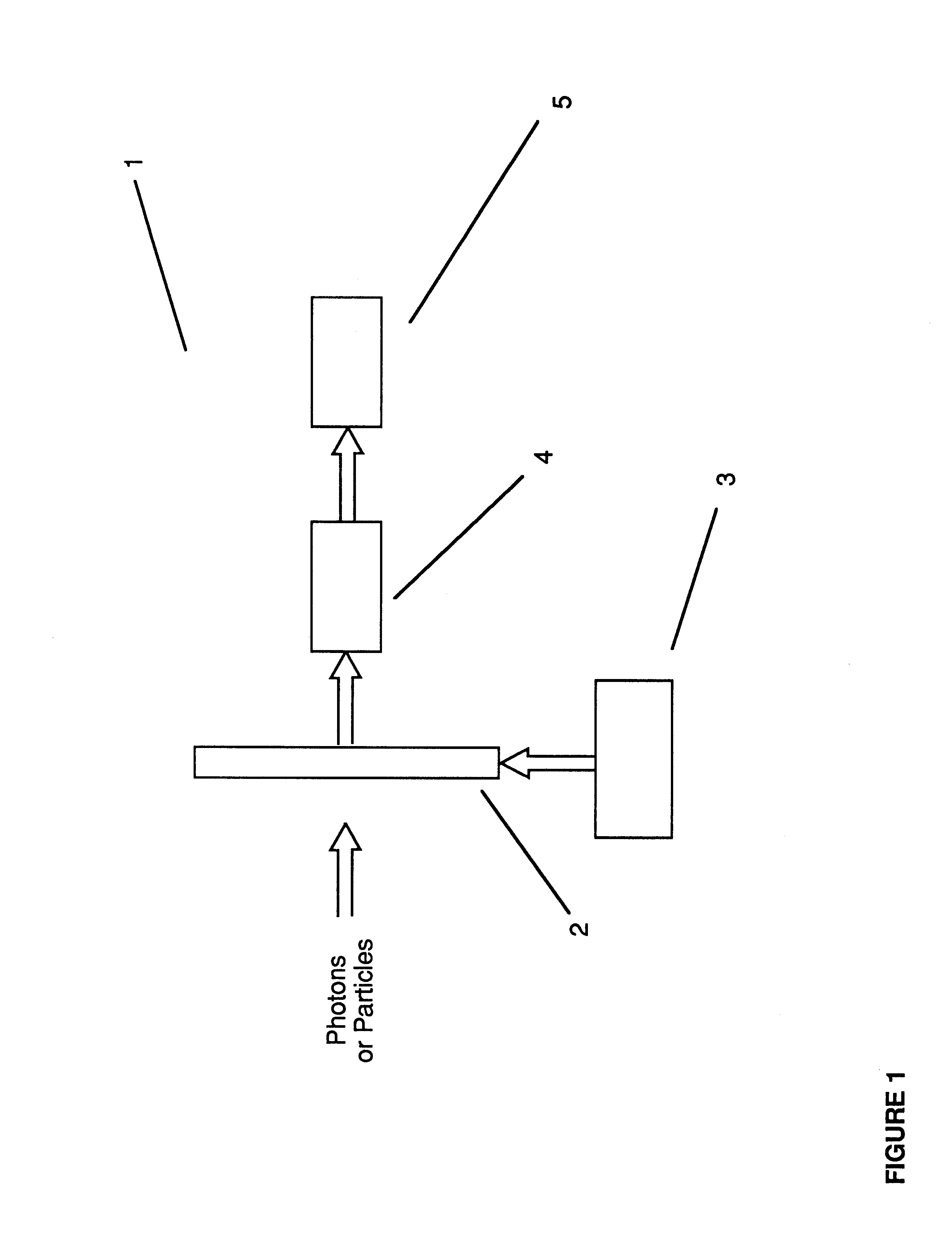
A preferred embodiment of the present invention, the High Data Rate Smart Sensor System (HDSS) 1 depicted in FIG. 1 block diagram, is designed to processes data generated by an array of detectors located in a sensor 2. This system 1 is further comprised of sensor drive electronics 3. The HDSS may further be comprised of digitizing and output electronics 4, a digital data processor and display 5.

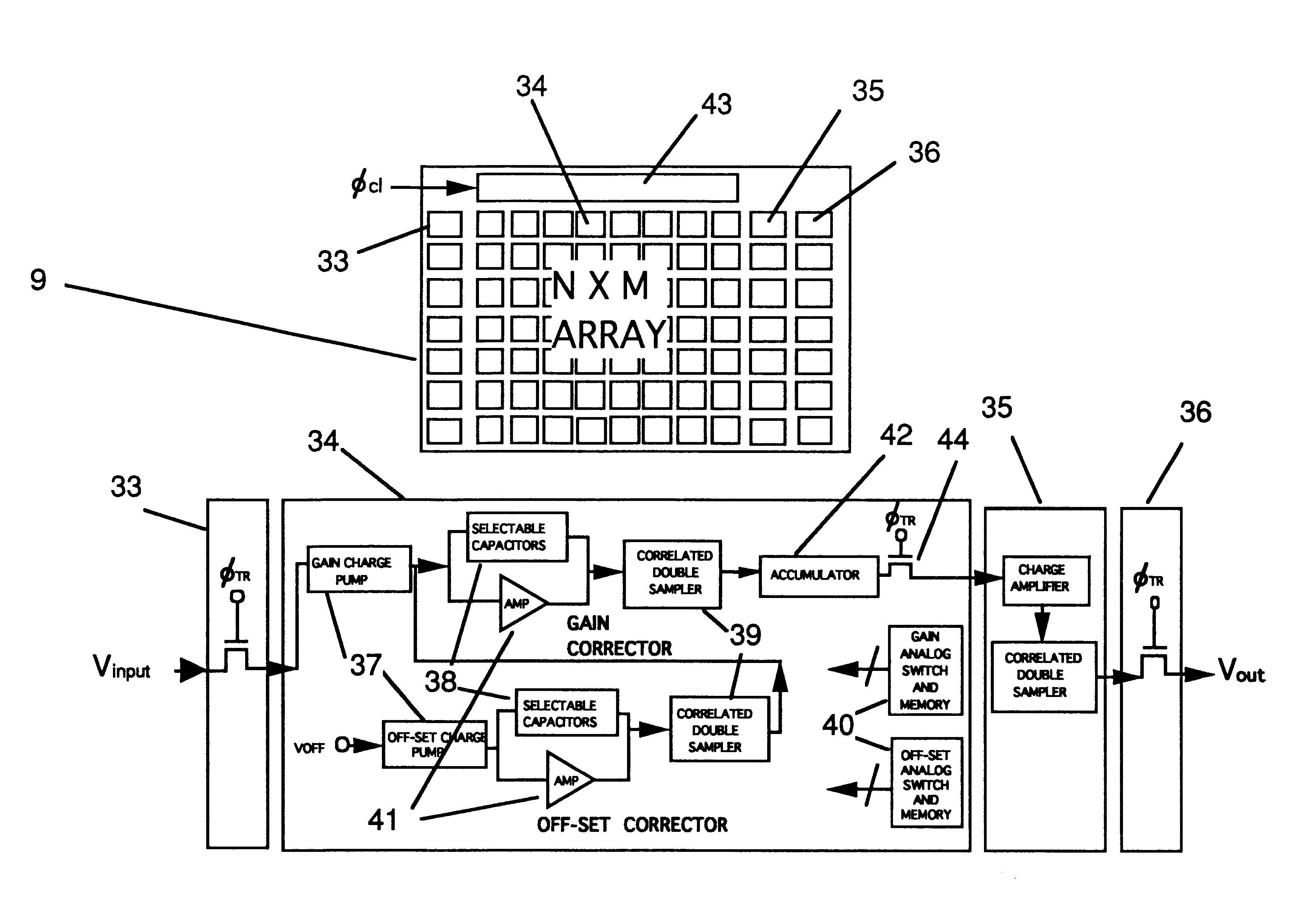
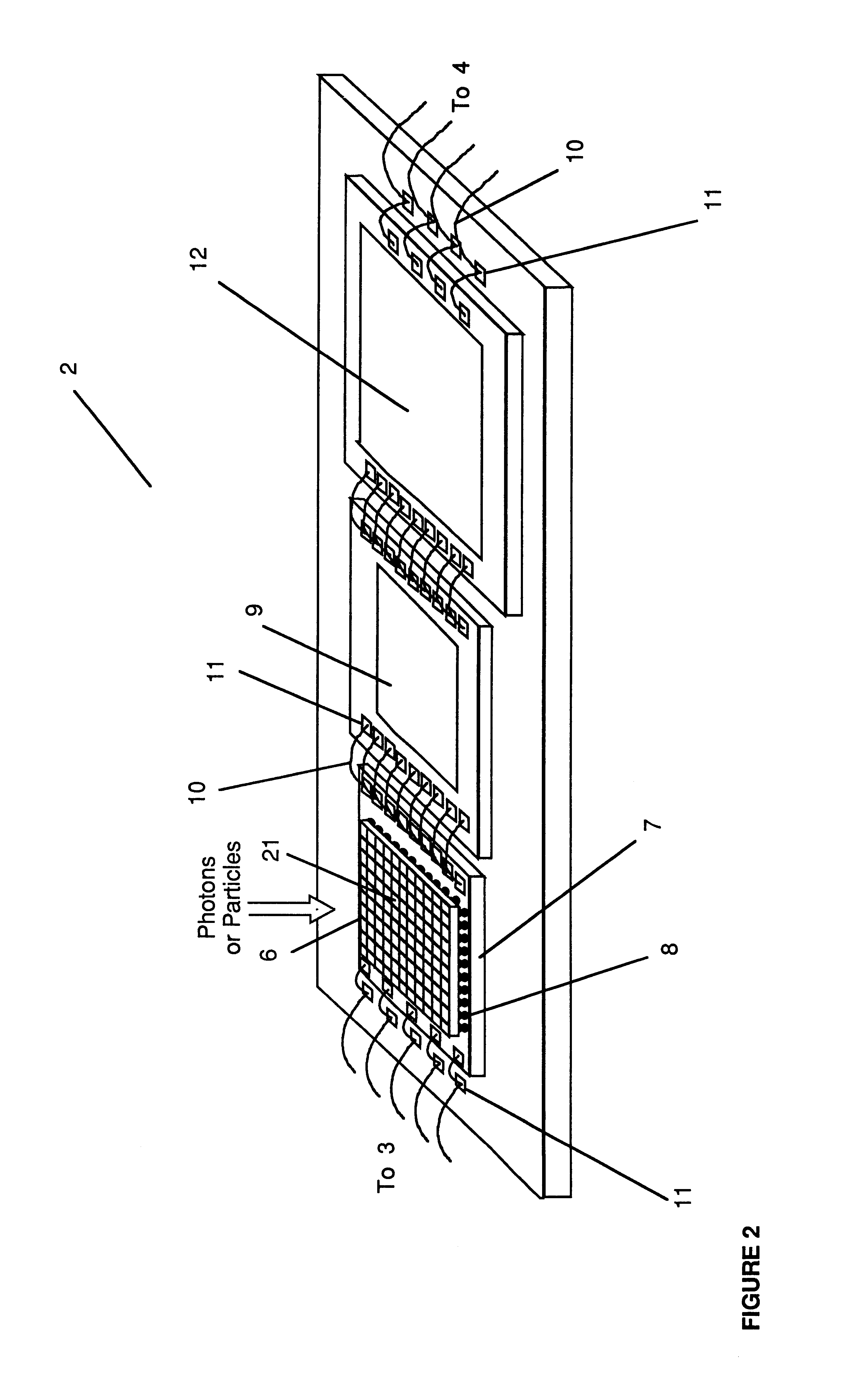
One embodiment of the sensor 2 is shown in FIG. 2. It is comprised of a detector array chip 6 connected to a readout array chip 7 by bump bonds 8; the readout array chip 7 is connected to an analog correction processor 9 by wire bonds 10 and bond pads 11. Typically the detector array is a PIN diode array made from solid-state materials such as silicon or germanium. The readout array chip may be, alternatively, connected to the analog correction processor by a interconnect chip which is bump bonded to both chips; bump bonds taking the place of wire bonds. The analog correction processor 9 may ...


PUM


Abstract

A device for the high-speed analysis of photon- or particle-generated image data or for the high-speed energy-discrimination analysis of photon- or particle-counting data. The device uses a sensor that collects the photons or particles on an array of solid state detectors, as electrical analog signals, and stores the analog-signal information on capacitors of readout arrays associated with the detector arrays. Integration of the photon or particle flux signals on the readout arrays proceeds for a given time frame and then image-related signals are transferred to an analog correction processor. The analog correction processor is comprised of one or more integrated circuit chips where each chip contains an array of correction processor unit cells. In these unit cells signals are corrected, in parallel, for gain and offset nonuniformities in the detection and processing chain. Corrections to all the signals are made in a time frame or less and the information is then transferred to an analog image processor. Particle-counting data is transferred directly from the readout array chips to the analog image processor. The analog image processor is comprised of one or more integrated circuit chips where each chip is made up of an array of image processor unit cells. Each unit cell contains circuitry for implementing an image processing or energy discrimination algorithm, and circuitry for outputting the signals and / or the position of only those unit cells for which the algorithm is satisfied. The analog image processor chip may also contain circuitry that counts the number of cells for which the algorithms have been satisfied. The analog image processor implements the algorithm and outputs the data in a time frame or less.

Description

Current large detector-array technologies, for particle or photon imaging or for counting, are frame rate or count rate limited. Examples of these detector array technologies are focal plane arrays used for visible and infrared light imaging and detector arrays used for x-ray florescent spectroscopy. The imaging speed limitation is usually related to the need to digitize all the data in the array and transfer it to a digital computer for processing. Digitizing and transferring all the data produces a data rate bottleneck and digitally processing all the data produces a processing rate bottleneck. High frame rates or count rates can currently be handled by massively-parallel digital processors. However, because of the shortcomings of these systems, namely high cost, large size and large-power consumption, this solution is not in common use.This invention relates to cameras or sensors using detector arrays and analogprocessing integrated-circuit architectures; the analog-processing ci...

Claims


Application Information

Patent Timeline
Patent Type & Authority Patents(United States)
IPC IPC(8): G01T1/00G01T1/20G01T1/164G01T1/24H01J1/02H01J1/34H01L27/146H01L27/148
CPCG01T1/1644G01T1/2018H01J1/34G01T1/247H01L27/146H01L27/14625H01L27/148H01J2201/3423H01J2231/50031H01J2231/50068H01J2231/5056H01J2231/50063H01L2224/48137H04N25/79
Inventor STETTNER, ROGERBAILEY, HOWARD W.
Owner CONTINENTAL ADVANCED LIDAR SOLUTIONS US LLC
Why Eureka
Try Eureka