Oxide magnetic material, ferrite particles, bonded magnet, sintered magnet, process for producing the same, and magnetic recording medium

a technology of oxide magnetic material and ferrite particles, which is applied in the direction of magnetic materials for record carriers, magnetic bodies, instruments, etc., can solve the problems of not considerably high, substantially impossible to provide a high br value of 4.5 kg or more, and difficult to obtain a br value of 4.4 kg or more and a hcj of 3.5 koe or more at the same time, and achieve excellent magnetic characteristics and high br value. , the effect of improving th

Inactive Publication Date: 2002-06-11
TDK CORPARATION
View PDF22 Cites 46 Cited by
  • Summary
  • Abstract
  • Description
  • Claims
  • Application Information

AI Technical Summary

Benefits of technology

The composition of the invention comprises a hexagonal Ca series ferrite, to which at least optimum amounts of R and M are added, as shown by the formulae described in the foregoing. By using this composition, excellent magnetic characteristics can be obtained, and at the same time, the temperature characteristics of HcJ can be considerably improved. Furthermore, in the case Co is used as M, while Is is not lowered, rather Is and K.sub.1 are simultaneously increased to increase H.sub.A, and thus a high Br value and a high HcJ value are realized. Specifically, in the sintered magnet of the invention where Co is used as M, the characteristics satisfying the equations (IV) and (V) above can be obtained at room temperature of about 25.degree. C. It has been reported that the conventional Sr ferrite sintered magnet exhibits Br of 4.4 kG and HcJ of 4.0 kOe, but none has been obtained that has HcJ of 4 kOe or more and satisfies the equation (IV). In other words, if HcJ is increased, Br must be low. In the sintered magnet of the invention, although the combination addition of Co and Zn lowers the coercive force lower than the case of the single addition of Co, in some cases lower than 4 kOe, the residual magnetic flux density is considerably increased. At this time, the magnetic characteristics satisfying the equation (V) are obtained. There has been no conventional Sr ferrite sintered magnet having HcJ of less than 4 kOe that satisfies the equation (V). Furthermore, in the invention, the temperature characteristics of HcJ are considerably improved in the case where Ni is added.
The M type ferrite of the invention having a composition where Co is used as M has a saturation magnetization (4.pi.Is) increased by about 2%, and a crystal magnetic anisotropy constant (K.sub.1) or an anisotropic magnetic field (H.sub.A) increased by 10 to 20% at most. As the precise measurement of the crystal magnetic anisotropy constant (K.sub.1) and the anisotropic magnetic field (H.sub.A) is not so easy, there has been no established measurement method, but there can be exemplified a method, in which a torque curve of the anisotropic sample is measured by a torque meter, and then analyzed, to obtain the crystal magnetic anisotropy constants (K.sub.1, K.sub.2, etc.), a method, in which the initial magnetization curve of the anisotropic sample is measured for the direction of an axis easily magnetized (c axis) and the direction of an axis hardly magnetized (a axis), and the anisotropic magnetic field (H.sub.A) is obtained from the point of intersection thereof, and a method, in which the anisotropic magnetic field (H.sub.A) is obtained from the differential of second order of the initial magnetization curve in the direction of an axis hardly magnetized (a axis).
When the anisotropic magnetic field H.sub.A of the invention is measured by the method, in which the initial magnetization curve of the anisotropic sample is measured for the direction of an axis easily magnetized (c axis) and the direction of an axis hardly magnetized (a axis), and the anisotropic magnetic field (H.sub.A) is obtained from the point of intersection thereof, a large value of at least 19 kOe or more, and further 20 kOe or more at most, can be obtained. This becomes an improvement by 10% at most in comparison to the Sr ferrite of the conventional composition.
While the invention exhibits a greater effect of enhancing the HcJ when applied to a sintered magnet, ferrite grains produced according to the invention can be mixed with a binder, such as plastics and rubber, to form a bonded magnet.
The ferrite grains and the sintered magnet of the invention have a small temperature dependency of HcJ, and particularly the ferrite grains of the invention have a considerably small temperature dependency of HcJ. Specifically, the sintered magnet of the invention has a temperature dependency of HcJ within a range of from -50 to 50.degree. C. of from -5 to 11 Oe / .degree. C. (0.23% / .degree. C. or less assuming that HcJ at 25.degree. C. is 3 kOe), which can be easily reduced to from -5 to 5 Oe / .degree. C. (0.17% / .degree. C. or less assuming that HcJ at 25.degree. C. is 3 kOe). The ferrite grains of the invention have an absolute value of a temperature coefficient of HcJ within a range of from -50 to 50.degree. C. of 5 Oe / .degree. C. or less (0.17% / .degree. C. or less assuming that HcJ at 25.degree. C. is 3 kOe), which can be easily reduced to 1 Oe / .degree. C. or less (0.04% / .degree. C. or less assuming that HcJ at 25.degree. C. is 3 kOe). It is possible that the temperature coefficient can be zero. Such superior magnetic characteristics under the low temperature environment cannot be attained by the conventional Sr ferrite magnet.
The invention involves a coating type magnetic recording medium having a magnetic layer comprising the ferrite grains dispersed in a binder. The invention also involves a magnetic recording medium having a thin film magnetic layer having the hexagonal magnetoplumbite ferrite phase as similar to the above-described magnet. In these cases, a magnetic recording medium of a high output and a high S / N ratio can be realized owing to the high residual magnetic flux density. Since the magnetic recording medium of the invention can be used as a magnetic recording medium for normal magnetic recording, the recording density can be high. Furthermore, since an absolute value of the temperature coefficient of HcJ can be small, a thermally stable magnetic recording medium can be realized.

Problems solved by technology

However, the magnetic characteristics obtained in this case is those equivalent to a Ba ferrite at most, which is not considerably high.
Therefore, Br of these magnets is limited to about 4.46 kG at most, and it has been substantially impossible to provide a high Br value of 4.5 kG or more.
In this case, however, since the anisotropic magnetic field (H.sub.A), which will be described later, is decreased, it is difficult to obtain a Br value of 4.4 kG or more and an HcJ of 3.5 kOe or more at the same time.
It has been known that the M type Sr ferrite has the largest K.sub.1 value, but it has been difficult to further raise the K.sub.1 value.
In this process, however, the HcJ value becomes 4.0 kOe when the Br value is 4.4 kG, and therefore it has been difficult to obtain a high HcJ of 4.5 kOe or more with maintaining a high Br of 4.4 kG or more at the same time.
The use of such fine grains brings about a problem in that the productivity is generally deteriorated due to increase in molding time and increase in generation of cracks on molding.
Thus, it has been very difficult to realize high characteristics and high productivity at the same time.
Powder of an isotropic M type ferrite has a temperature dependency of HcJ of at least about +8 Oe / .degree. C., although it is superior to the anisotropic sintered magnet, and a temperature coefficient of +0.15% / .degree. C., and thus it has been difficult to further improve the temperature characteristics.
In this case, however, HcJ at room temperature is also decreased, and thus the high HcJ at room temperature and its temperature characteristics cannot be improved at the same time.

Method used


Image

  • Oxide magnetic material, ferrite particles, bonded magnet, sintered magnet, process for producing the same, and magnetic recording medium
  • Oxide magnetic material, ferrite particles, bonded magnet, sintered magnet, process for producing the same, and magnetic recording medium
  • Oxide magnetic material, ferrite particles, bonded magnet, sintered magnet, process for producing the same, and magnetic recording medium

Examples


example

Example 1

A Sintered Magnet Produced by Sintering a CaLaCo Ferrite (z=1) in the air or in Oxygen

Raw materials were weighed and mixed, so that a mixture had a composition with a Ca / La / Co / Fe ratio of Ca.sub.1-x1 La.sub.x1 Fe.sub.12-x1 Co.sub.x1, wherein x=y=0 to 1, and Z=1. The raw materials used were .alpha.-Fe.sub.2 O.sub.3 (for industrial use), La.sub.2 O.sub.3 (99.9%), CaCO.sub.3 and cobalt oxide (reagent, mixture of 85% of Co.sub.3 O.sub.4 and 15% of CoO). At this time, SiO.sub.2 (0.4% by weight) was simultaneously added. The weighed raw materials were mixed in a wet attritor, followed by drying. The resulting mixed powder was calcined with a batch furnace at 1,200.degree. C. for 3 hours in the air.

To the calcined powder, SiO.sub.2 (0.4% by weight), CaCO.sub.3 (1.25% by weight) and 1 ml of ethanol were added, and the mixture was pulverized with a dry vibration rod mill for 20 minutes. To the pulverized powder, 1.3% by weight of oleic acid was added, and the mixture was pulverized ...

example 2

A sintered magnet produced by Sintering a CaLaCo Ferrite with the z Value Deviated (z=0.85 or 0.95)

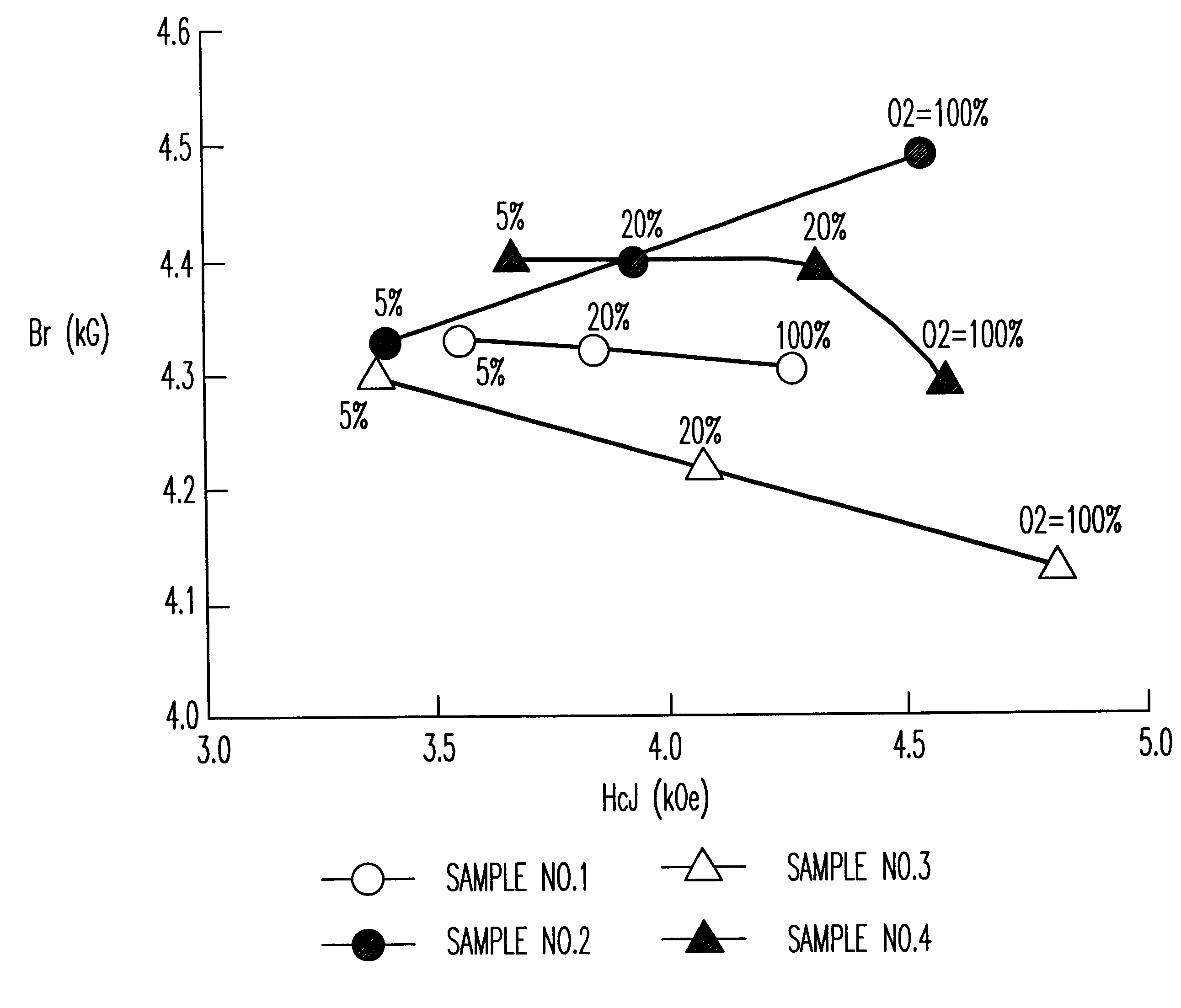
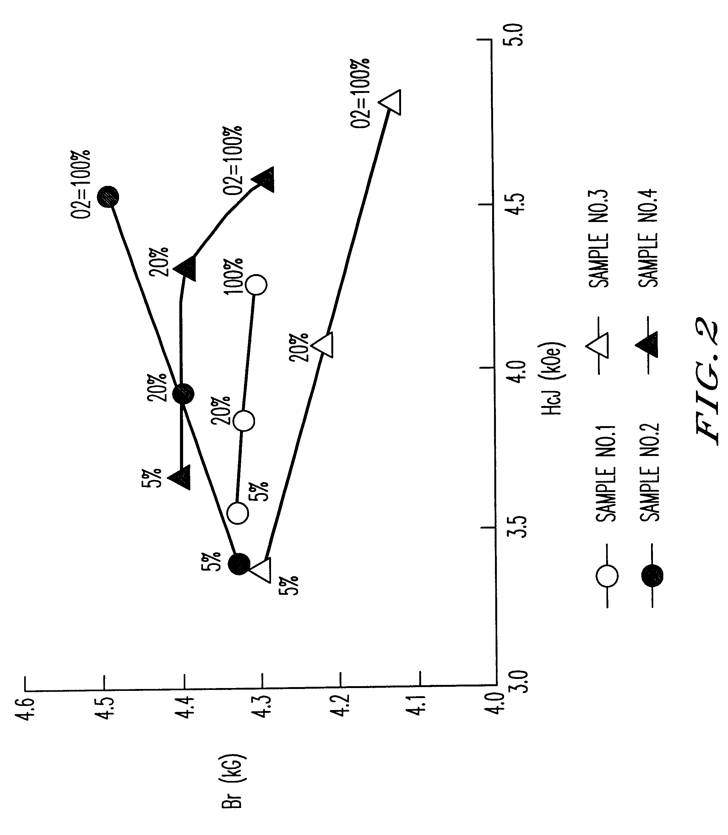
Samples of sintered bodies were produced in the same manner as in Example 1 except that the calcining temperature was 1200.degree. C. and the compositions and the addition conditions shown in Table 1 were employed. The magnetic characteristics of the sintered bodies with the sintering temperature of 1,220.degree. C. and in various sintering atmospheres are shown in FIG. 2. The magnetic characteristics of Sample No. 2 in Table 1 where the sintering temperature is 100% oxygen and the sintering temperature is varied from 1,200 to 1,240.degree. C. are shown in Table 2.

TABLE 1

It is clear from FIG. 2 that Sample No. 2 (z=0.85,1% by weight of CaCO.sub.3 was added after the calcination) sintered in oxygen exhibited superior characteristics (Br of 4.5 kG and HcJ of 4.5 kOe) equivalent to an SrLaCo series ferrite. Furthermore, it was clear from Table 2 that when the sintering atmosphere was oxyg...

example 3

The Calcined Material and the Pulverized Material Observed with an SEM

The calcined material of x=y=0.5 and z=0.85 calcined at 1,250.degree. C. and its pulverized material pulverized with a ball mill were observed with an SEM. The resulting photographs are shown in FIGS. 3 to 5. FIG. 3 is a photograph of the surface of the calcined material grains, FIG. 4 is an enlarged photograph of FIG. 3, and FIG. 5 is a photograph of the powder pulverized with a ball mill for 40 hours. It was clear from FIGS. 3 and 4 that the primary particles of the calcined material were plate-like crystals having an extremely large aspect ratio having a thickness of 1 .mu.m and a grain diameter of from 3 to 10 .mu.m. Furthermore, an extremely unique state was observed in that the particles were oriented within the region having a width of from 10 to 20 .mu.m. It was clear from FIG. 5 that the powder after pulverization with a ball mill had a size of about 1 .mu.m or less.


PUM

PropertyMeasurementUnit
pressureaaaaaaaaaa
partial pressureaaaaaaaaaa
crystal grain sizeaaaaaaaaaa

Abstract

The present invention provides an oxide magnetic material, which includes a primary phase of a hexagonal ferrite containing metallic elements Ca, R, Fe and M, where M represents at least one element selected from the group including Co, Ni and Zn, and R represents at least one element selected from the group including Bi and rare earth elements including Y, with La being essentially included in R; wherein the proportions of the metallic elements Ca, R, Fe and M with respect to the total amount of the metallic elements are from 1 to 13 atomic % for Ca, from 0.05 to 10 atomic % for R, from 80 to 95 atomic % for Fe, and from 1 to 7 atomic % for M. The present invention also provides ferrite particles, a bonded magnet, a sintered magnet, a process for producing them, and a magnetic recording medium, which contain the oxide magnetic material.

Description

The present invention relates to magnet powder and a sintered magnet comprising a hexagonal ferrite, a bonded magnet and a magnetic recording medium comprising the magnet powder, and a magnetic recording medium having a thin film magnetic layer comprising a hexagonal ferrite phase.TECHNICAL BACKGROUNDAs a material for an oxide permanent magnet, a magnetoplumbite (M type) hexagonal strontium (Sr) ferrite or barium (Ba) ferrite has been mainly used. Calcium (Ca), which is one of the alkaline earth elements as similar to Ba and Sr, has not been used as a magnet material though it is not expensive because Ca does not form a hexagonal ferrite.In general, a Ca ferrite has a stable structure of CaO-Fe.sub.2 O.sub.3 or CaO-2Fe.sub.2 O.sub.3, and does not form a hexagonal ferrite (CaO-6Fe.sub.2 O.sub.3), but it has been known that a hexagonal ferrite is formed by adding La. In this case, it is considered that the valence of a part of the Fe ion is changed (Fe.sup.3+ to Fe.sup.2+) to compensa...

Claims


Application Information

Patent Timeline
Patent Type & Authority Patents(United States)
IPC IPC(8): C04B35/26G11B5/64H01F1/032G11B5/706H01F1/11H01F1/10H01F1/113
CPCC04B35/2633C04B35/2641G11B5/653H01F1/113G11B5/70678H01F1/10H01F1/11G11B5/656
Inventor TAGUCHI, HITOSHIMASUZAWA, KIYOYUKIMINACHI, YOSHIHIKOIIDA, KAZUMASAKAWAKAMI, MIYUKI
Owner TDK CORPARATION
Why Eureka
Try Eureka