
Nitride type, rare earth magnet materials and bonded magnets formed therefrom

a rare earth magnet material and nitride technology, applied in the direction of magnetic materials, inorganic material magnetism, magnetic bodies, etc., can solve the problems of drastic deterioration of the magnetic properties of sm.sub.2 fe.sub.17 n.sub.x compounds, and the application of high temperatures is restricted

Inactive Publication Date: 2002-07-02
HITACHI METALS LTD
View PDF12 Cites 25 Cited by
  • Summary
  • Abstract
  • Description
  • Claims
  • Application Information

AI Technical Summary

Benefits of technology

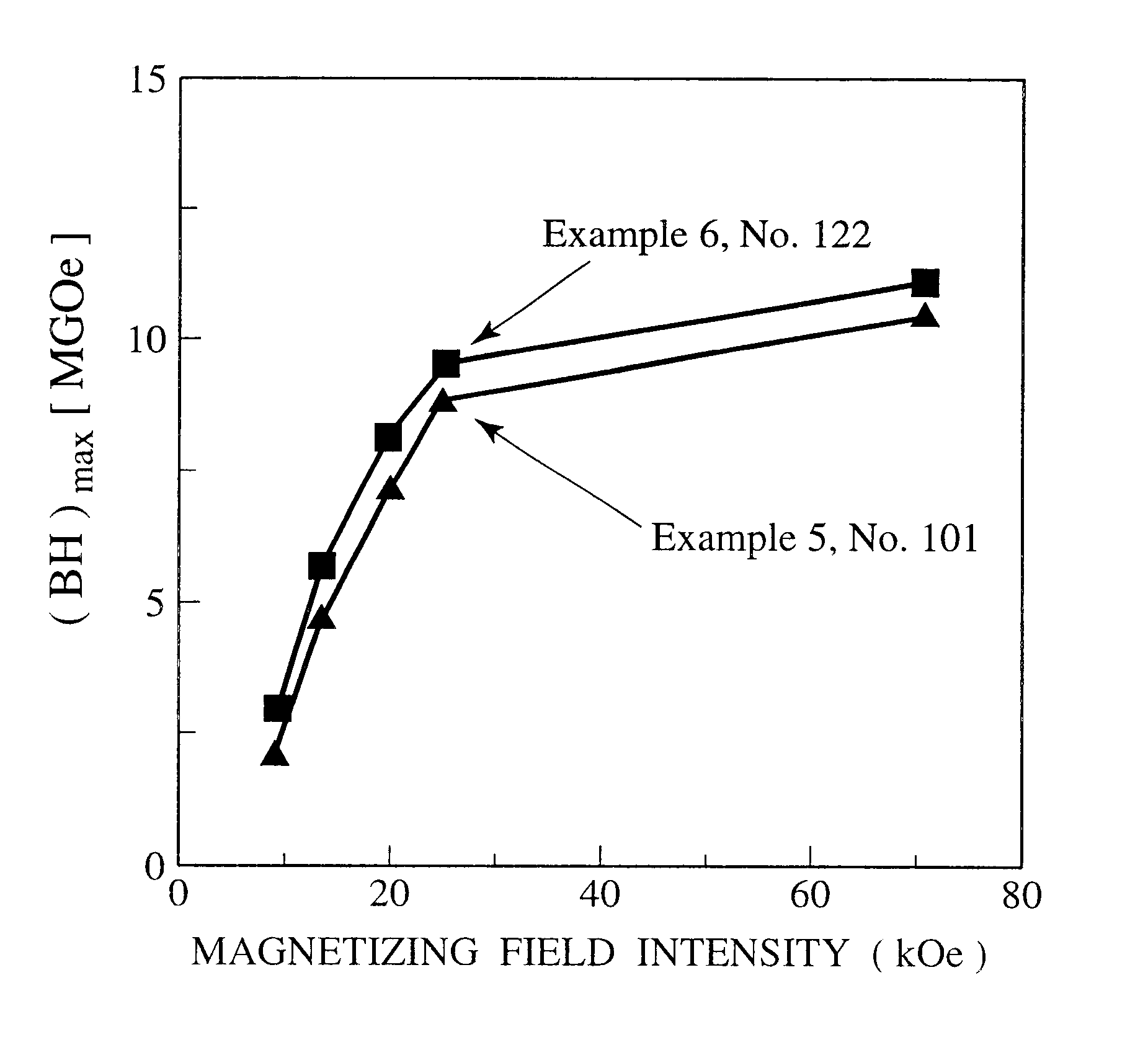
Another object of the present invention is to provide an isotropic, bonded rare earth magnet containing such a nitride-type, rare earth magnet material and having good magnetizability.
(2) To provide a small decrease in magnetic properties by temperature elevation (good heat resistance);
(4) To easily form isotropic, bonded rare earth magnets under practical molding pressure;
It has particularly been found that nitride-type, rare earth magnet materials satisfying the above requirements (1)-(6) can be produced by rapidly cooling a mother alloy melt having a composition corresponding to the basic composition of an R--T--M--B--N nitride-type, magnet alloy, wherein R is at least one rare earth element including Y, as a rare earth element Sm must be present, T is Fe alone or a combination of Fe and Co and / or Ni, and M is at least one element selected from the group consisting of Al, Ti, V, Cr, Mn, Cu, Ga, Zr, Nb, Mo, Hf, Ta, W and Zn, wherein Ti must be present, at a peripheral speed of a quenching roll that is preferably 0.05-15 m / second, more preferably 0.08-10 m / second, particularly preferably 0.1-8 m / second, and then subjecting the resultant quenched alloy to a hydrogenation / decomposition reaction treatment and a dehydrogenation / recombination reaction treatment described below, and then to a nitriding treatment. It has further been found that a combination of Sm and La is advantageously selected as the R element to improve the magnetizability. The present invention has been completed based on these findings.
The mother alloy subjected to the dehydrogenation / recombination reaction is then pulverized to a desired particle size, if necessary. Particularly when the mother alloy is a thin ribbon obtained by a strip-casting method, it is preferably pulverized to a predetermined average particle size. Also, the classification or sieving of the pulverized mother alloy is carried out, if necessary, to adjust its particle size distribution. This is preferable, because it provides a uniform nitride structure, resulting in improved moldability and density of a bonded magnet.
When a compression-molding method is utilized, thermosetting resins are preferable, and liquid thermosetting resins are particularly suitable. Specific examples of preferable liquid thermosetting resins are liquid epoxy resins, for the reasons of low cost, easy handling and good heat resistance of the molded products.

Problems solved by technology

Bonded rare earth magnets comprising Nd--Fe--B magnet powder have conventionally been used widely, though their applications at high temperatures are restricted because they have as low Curie temperatures as about 300.degree. C. and high temperature coefficients of coercivity iHc.
However, Sm.sub.2 Fe.sub.17 N.sub.x compounds fail to show usefully high iHc unless they are pulverized to as small a particle size as a few .mu.m, corresponding to the size of a single magnetic domain.
Also, Sm.sub.2 Fe.sub.17 N.sub.x compounds in a state of fine powder having a few .mu.m size are easily oxidized in the air at room temperature, resulting in drastic deterioration of their magnetic properties.
In addition, Sm.sub.2 Fe.sub.17 N.sub.x compounds in a state of fine powder having a few .mu.m cannot be filled in the bonded magnets at high density, failing to achieve usefully high maximum energy products (BH).sub.max.
However, because thin mother alloy ribbons rapidly-quenched under the above conditions are extremely as thin as less than 50 .mu.m, magnet powders obtained by finally nitriding them have ragged shapes, reflecting the shapes of the thin ribbons.
As a result, such magnet powders cannot be compression-molded well.
However, conventional R--T--M--N-type, isotropic, bonded rare earth magnets are not well magnetized under the above conditions.

Method used


Image

  • Nitride type, rare earth magnet materials and bonded magnets formed therefrom
  • Nitride type, rare earth magnet materials and bonded magnets formed therefrom
  • Nitride type, rare earth magnet materials and bonded magnets formed therefrom

Examples


example 2

To observe the correlation of the B content and magnetic properties, component elements were formulated in such proportions as to provide basic compositions of Nos. 31-34 shown in Table 2, and nitride-type, rare earth magnet material powders were produced in the same manner as in EXAMPLE 1. Each of the resultant nitride-type, rare earth magnet material powders had dp.sub.av of 80 .mu.m. Each nitride-type, rare earth magnet material powder was evaluated in the same manner as in EXAMPLE 1. The results are shown in Table 2 as Nos. 31-34.

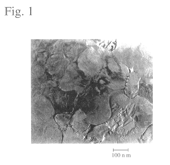
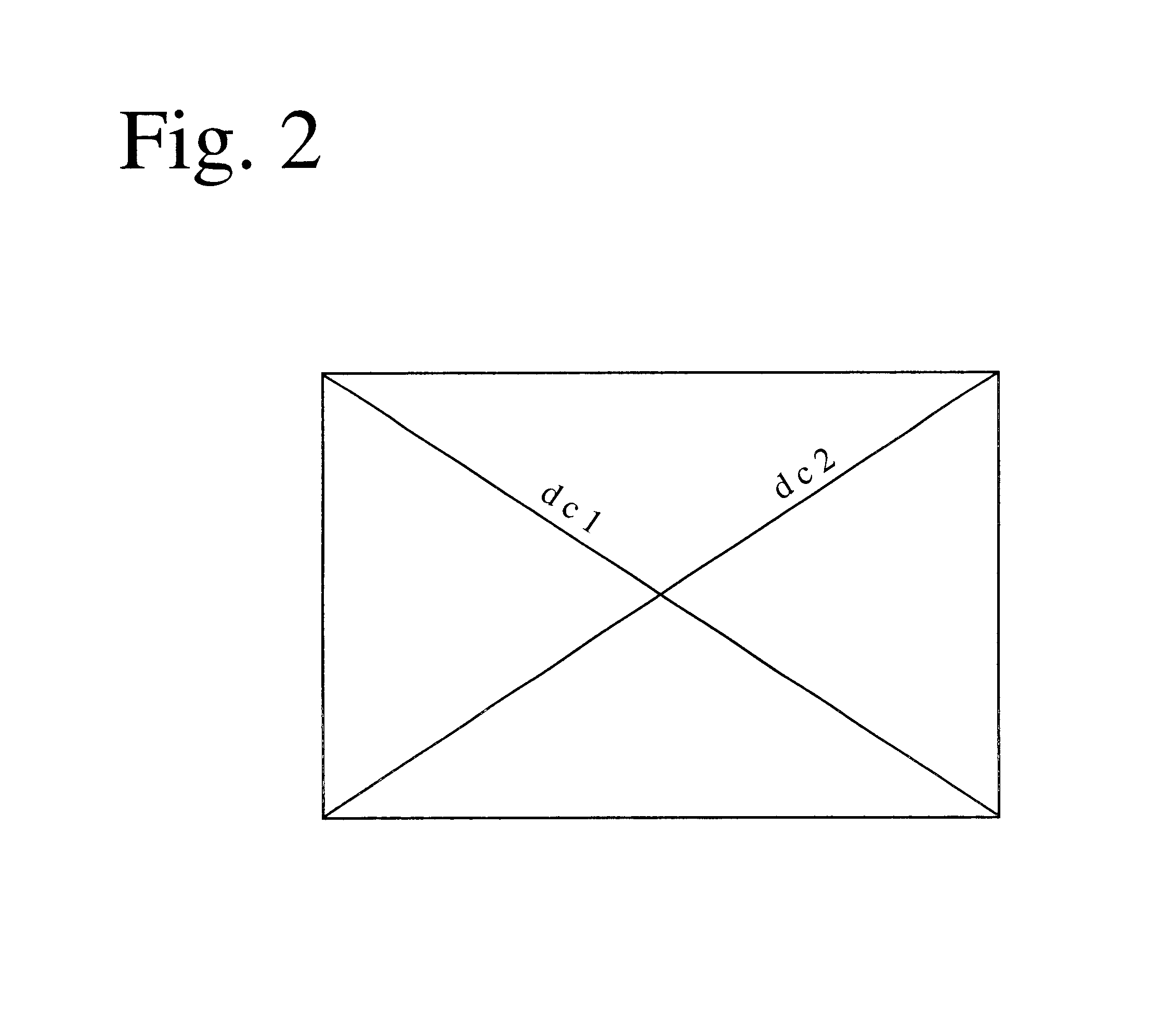
A sample for measuring dc.sub.av was produced from the nitride-type, rare earth magnet material powder of No. 33, and its transmission electron microscopic photograph was taken in arbitrarily selected five view fields. FIG. 1 shows one of the resultant TEM photographs, and FIG. 2 explains how dc.sub.av was determined with respect to the nitride-type, rare earth magnet material powder of FIG. 1. Diagonal lines were drawn in each TEM photograph in five vi...

example 3

Comparative Example 4

To evaluate magnetic properties with varied types and contents of R, varied contents of nitrogen, and varied types and contents of M, and with Fe partially substituted by Co and / or Ni, nitride-type, rare earth magnet material powders were produced in the same manner as in EXAMPLE 1 except for having the basic compositions shown in Table 3. Each nitride-type, rare earth magnet material powder was evaluated in the same manner as in EXAMPLE 1. The results are shown in Table 3.

It was confirmed from Table 3 that any of the nitride-type, rare earth magnet material powders of EXAMPLE 3 had a structure composed of a fine hard magnetic phase of an R.sub.2 T.sub.17 -type structure free from .alpha.-Fe.

It is clear from Nos. 51-53 in EXAMPLE 3 and Nos. 71-73 in COMPARATIVE EXAMPLE 4 that when the percentage of Sm in the R components is 50 atomic % or more, and when the R components are 6-15 atomic %, good .sigma., iHc and .eta. are obtained.

It is clear from Nos. 54 and 55 i...

example 4

Sm, Fe, Ti and B each having a purity of 99.9% or more were formulated to a composition corresponding to the basic composition described below, and melted in a high-frequency furnace in an argon gas atmosphere. The resultant mother alloy melt was rapidly quenched by cooling rolls at a peripheral speed of 9.5 m / second, thereby obtaining a thin mother alloy ribbon having a thickness of 250-300 .mu.m. This thin mother alloy ribbon was placed in an atmosphere-controlled heat treatment furnace, and repeated the step of heating to 500.degree. C. while supplying a hydrogen gas at 1 atm to have the alloy to absorb hydrogen and the step of evacuating to carry out dehydrogenation, thereby coarsely pulverizing the alloy to an average particle size of 100 .mu.m.

The resultant powder was subjected to a hydrogenation / decomposition reaction treatment under the heating conditions shown in Table 4 at a hydrogen gas pressure of 1 atm. It was then subjected to a dehydrogenation / recombination reaction t...


PUM


Abstract

A nitride-type, rare earth magnet material having a basic composition represented by RalphaT100-(alpha+beta+gamma+delta)MbetaBgammaNdelta (atomic %), wherein R is at least one rare earth element including Y, as a rare earth element Sm must be present, T is Fe alone or a combination of Fe and Co and / or Ni, M is at least one element selected from the group consisting of Al, Ti, V, Cr, Mn, Cu, Ga, Zr, Nb, Mo, Hf, Ta, W and Zn, 6<=alpha<=15, 0.5<=beta<=10, 0<=gamma<=4, and 4<=delta<=30, which is substantially composed of a hard magnetic phase of an R2T17-type structure having an average crystal grain size of 0.01-1 mum, an average area ratio of alpha-Fe being 5% or less.

Description

The present invention relates to a nitride-type, rare earth magnet material made of an R--T--M(--B)--N alloy and an isotropic, bonded rare earth magnet formed from such a nitride-type, rare earth magnet material, particularly to a nitride-type, rare earth magnet material comprising Sm and La as R and an isotropic, bonded rare earth magnet having good magnetizability.Bonded rare earth magnets comprising Nd--Fe--B magnet powder have conventionally been used widely, though their applications at high temperatures are restricted because they have as low Curie temperatures as about 300.degree. C. and high temperature coefficients of coercivity iHc.Sm.sub.2 Fe.sub.17 N.sub.x compounds formed by making Sm.sub.2 Fe.sub.17 compounds absorb nitrogen have recently been finding industrial applications as magnet powder for bonded magnets, because they show higher Curie temperatures (470.degree. C.) and anisotropic magnetic field (260 kOe) than those of Nd.sub.2 Fe.sub.14 B compounds. However, Sm....

Claims


Application Information

Patent Timeline
IPC IPC(8): H01F1/032H01F1/059
CPCH01F1/059H01F1/0596H01F1/06
Inventor OKAJIMA, HIROSHITOBISE, MASAHIROSHINDO, MIKIO
Owner HITACHI METALS LTD
Learn More