Electrode for battery, method of manufacturing the same and battery

a technology of electrodes and batteries, applied in sustainable manufacturing/processing, non-aqueous electrolyte cells, cell components, etc., can solve the problems of inability to weld tabs with thin film collectors, and inability to meet the requirements of large-scale welding devices

Inactive Publication Date: 2002-09-10
TDK CORPARATION
View PDF5 Cites 43 Cited by
  • Summary
  • Abstract
  • Description
  • Claims
  • Application Information

AI Technical Summary

Benefits of technology

Thus, the object of the present invention is to provide, upon solving the problems of the prior art, an electrode for a battery in which a collector and an electrode tab are connected by a novel connection structu

Problems solved by technology

However, a large-sized welding device is required.
Moreover, as described in, for example, Japanese Laid-Open Patent Publication No. 9-213,338/1997, when a collector is formed as a thin film on a resin film or a resin sheet, it is almost impossible to weld a tab with this thin film collector.
When connection is conducted with an adh

Method used


Image

  • Electrode for battery, method of manufacturing the same and battery
  • Electrode for battery, method of manufacturing the same and battery

Examples


example 1

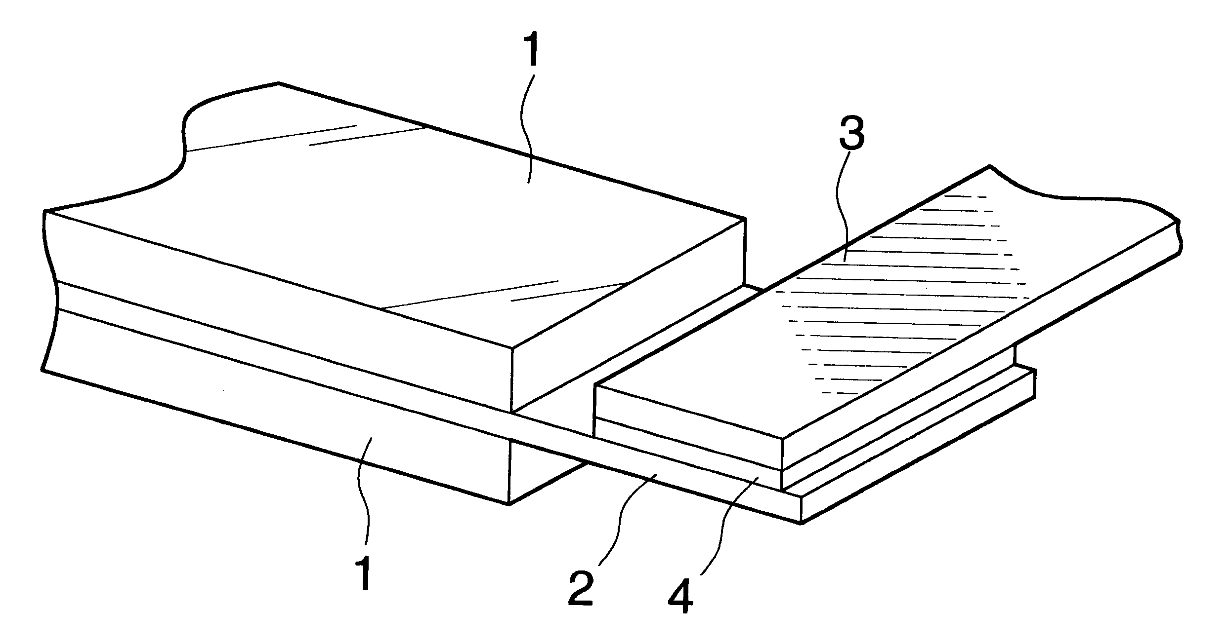
A negative electrode of a connection structure shown in FIG. 1 was manufactured. That is, FIG. 1 is a partial perspective view showing a connection structure of a collector and a tab of an electrode manufactured in Example 1.

(Formation of an active material layer (1) on a collector (2))

As shown in Table 1, 8 parts by weight of the binder was dissolved in 150 parts by weight of the solvent NMP (N-methylpyrrolidone), and 86 parts by weight of the active material and 6 parts by weight of the pulverized product of expanded graphite were added. These were mixed with a hyper-mixer. Subsequently, the mixture was subjected to an ultrasonic dispersing machine to form a coating-material. The coating-material is applied onto one surf ace of a strip collector (2) made of a copper foil having a thickness of 18 .mu.m, and dried to form an active material layer. In the same manner, an active material layer was formed on another surface of the copper foil. The coating amount was the same on both th...

example 2

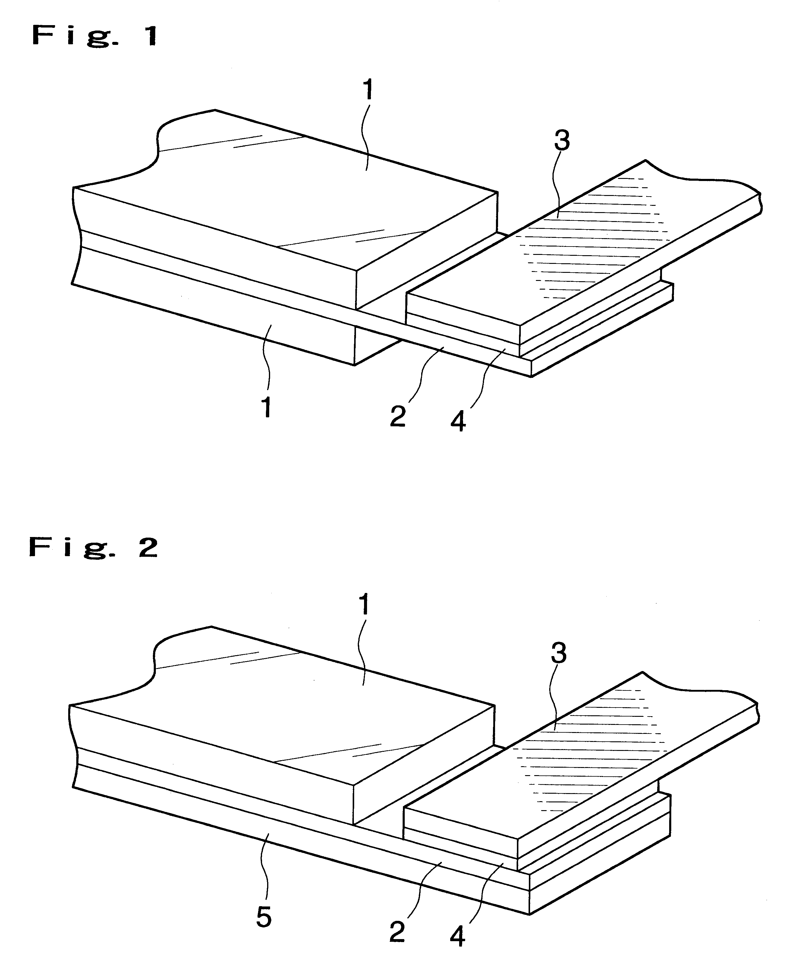
A positive electrode of a connection structure shown in FIG. 2 was manufactured. That is, FIG. 2 is a partial perspective view showing a connection structure of a collector and a tab of an electrode manufactured in Example 2.

In this Example, a product in which aluminum was deposited to a thickness of 1 .mu.m on a PET film (5) having a thickness of 11 .mu.m was used as a collector (2).

(Formation of an active material layer (1) on a collector (2))

As shown in Table 3, 4 parts by weight of the binder was dissolved in 67 parts by weight of the solvent, and 88 parts by weight of the active material (LiNi.sub.0.8 Co.sub.0.2 O.sub.2) and 8 parts by weight of the conductive agent were added. These were mixed with a hyper-mixer. Subsequently, the mixture was subjected to an ultrasonic dispersing machine to form a coating-material. The coating-material was applied onto the collector (2) formed on the PET film (5), and dried to form an active material layer. The coating amount was 20 mg per cm....


PUM


Abstract

An electrode for a battery in which a collector and an electrode tab are connected with a novel connection structure without impairing electrical connection, and a method of manufacturing the electrode quite simply are provided. Further, a battery having this electrode for the battery is provided. A collector (2) and a tab (3) are connected via a graphite layer (4). The graphite layer is formed on the surface of the collector to be connected with the tab and/or the surface of the tab to be connected with the collector, the portions to be connected of the collector and the tab are overlapped on each other with the graphite layer interposed between the collector and the tab, and a pressure is applied to the overlapped portions to connect the collector (2) with the tab (3). It is preferable that the collector (2) is made of a conductive thin film formed on a resin film (5).

Description

The present invention relates to an electrode for a battery in which an electrode tab is connected, a method of manufacturing the same, and a battery having the electrode. The present invention is characterized by a novel connection structure and a connection method of a collector and an electrode tab.The tab referred to in the present invention is generally called a (positive electrode or negative electrode) reed, a connection reed, a (positive electrode or negative electrode) terminal or the like, and it is contacted or connected with the collector to provide electrical connection between the collector and the outside.According to miniaturization and weight reduction of electronic appliances such as various OA appliances, VTR cameras, portable phones and the like in recent years, a high performance of a secondary battery used in these electronic appliances has been required. In order to meet such a requirement, the development of a lithium ion secondary battery that occludes or re...

Claims


Application Information

Patent Timeline
IPC IPC(8): H01M10/04H01M4/04H01M2/26H01M4/62H01M2/30H01M10/36H01M10/40H01M4/13H01M4/139H01M4/66H01M4/86H01M6/16H01M10/05H01M10/0525H01M10/058H01M50/531
CPCH01M2/26H01M4/04H01M4/625H01M10/0436H01M2/30H01M10/0525Y02E60/122Y02E60/10H01M50/531Y02P70/50H01M4/13H01M4/139
Inventor IIJIMA, TADAYOSHI
Owner TDK CORPARATION
Why Eureka
Try Eureka