
Method for determining the glucose content of a blood sample

a blood sample and glucose content technology, applied in the direction of biochemistry equipment, biochemistry equipment and processes, material testing goods, etc., can solve the problems of high power consumption, insufficient methods, and delay until the measurement actually started

Inactive Publication Date: 2002-09-10
77 ELEKTRONIKA MUSZERIPARI
View PDF14 Cites 70 Cited by
  • Summary
  • Abstract
  • Description
  • Claims
  • Application Information

AI Technical Summary

Benefits of technology

This is achieved in newer devices by measuring quasi-continuously the reflection curve, and by determining dynamically the Final measurement time. This latter process contradicts the requirement for simple operations and calculations. This is an important aspect, because the blood glucose measurement devices should be small and portable (i.e., operating from battery), be simple to operate, and, last but not least, be cheap.
A continuous reflection measurement requires the continuous or frequent switching on / off of the light source, typically a LED, and inevitably have a high power consumption. Therefore, it is sought to substitute the continuous measurement with sampling on a frequency as low as possible. It may also be mentioned that a more complicated method requires a more sophisticated controlling processor, which is more expensive. On the other hand, a more complicated algorithm, in a given processor in a given time, allows the evaluation of fewer measurement points, which in turn will result in a less precise measurement. It is less significant, but may be taken into consideration that the power consumption of the processor is higher with more calculating steps. This latter factor may play a role if the controlling algorithm of the device is not made by digital processor but by analog circuits, e.g. due to considerations of reliability. With higher power consumption the device will operate for a shorter time, so indirectly its reliability will worsen (i.e. the probability of malfunction due to the run-down of the batteries will increase).
Therefore, it is an object of the present invention to provide a method, which allows the determination of the measurement time in a manner avoiding or at least minimizing the disadvantages of the known solutions. Further objectives of the present invention are to determine the measurement time with a simple algorithm, and to determine a measurement time, which is set at or near the ideal time, dependent on the glucose content to be measured. It is still a further object to provide a method where the sampling frequency may be kept relatively low, in order to keep the power consumption low. Because the light sources of the measurement devices are normally the largest energy users, this is an important factor. The blood glucose measurements are also negatively affected by temperature variations, hence it is preferable that the method of the invention should deliver results independent of the measurement temperature.
On the other hand, when the actual values are determined by interpolating the measured values, then the method according to the present invention may be applied advantageously for the so-called quick strips, where the reactions take place quickly. For example, the sampling frequency can be reduced so that the T.sub.m time point is made equal not to the n-th value T.sub.n in which T.sub.n time we would first observe the reaching of the C(t) function, but the exact value of T.sub.m can be a point of time determined by interpolating between the time T.sub.n and T.sub.n-1, where T.sub.m is defined by the F*(T.sub.m)=C value. Here, the function F*(t) is the linear or higher order approximation of the function F(t)=R(t)+L(t)-ext[R(t)-L(t)] laid through points T.sub.n-1, F(T.sub.n-1) and T.sub.n, F(T.sub.n). Of course, the measured reflection value R.sub.m can also be calculated from the reflection values R(T.sub.n) and R(T.sub.n-1) by interpolation. The error caused by the interpolation will be very small because in this time interval the variation of R is quite low. A further benefit is that the procedure is less sensitive to the deviations caused by the fluctuation of the reaction rate, because it adjusts the measurement according to the variation in the reaction rate. Therefore, the aging of the test strips, the measurement temperature, vapor content and other factors affecting the reaction rate will but slightly deteriorate the accuracy of the glucose content measurement.
In one exemplary embodiment of the method according to the present invention, L(t) is a linear function with a predetermined slope [L(t)=At+B, preferably L(t)=At and B=O], while C(t) is a constant function [C(t)=C]. However, it is also possible that L(t) is a second-order or a higher order function of time. C(t) can be specified, for example, in a more general polynomial form as well. Preferably, the wetting through of the sample is detected on the basis of a predetermined amount of change in reflection. This requires merely a comparison with a threshold value, therefore, its demand for processing power is rather modest. However, it may be more advantageous if the wetting through of the sample is detected by a predetermined rate of change in reflection. With this method it is possible to filter out the effects of, for example, the inadvertent moving of the sample and the reductions in reflection not involving a real reaction. Alternatively, the wetting of the sample may be detected on the basis of the reflection value reaching a predetermined limit value. This simplifies the programming of the processor, because in the starting phase it requires the storing of a single reflection value at one time.

Problems solved by technology

This method was not adequate, because the delays until the measurement actually started were varying, due to the switching on, even with by same person.
A continuous reflection measurement requires the continuous or frequent switching on / off of the light source, typically a LED, and inevitably have a high power consumption.
It may also be mentioned that a more complicated method requires a more sophisticated controlling processor, which is more expensive.
On the other hand, a more complicated algorithm, in a given processor in a given time, allows the evaluation of fewer measurement points, which in turn will result in a less precise measurement.
With higher power consumption the device will operate for a shorter time, so indirectly its reliability will worsen (i.e. the probability of malfunction due to the run-down of the batteries will increase).
), because of the delay between the wetting of the sample carrier with the urine and placing the sample carrier in the device.
This method effectively excludes the subjective elements of the measurement, but its disadvantage is that the measurement time is determined independently of the glucose content.
It is a further disadvantage that it needs frequent samplings, to determine the exact time of wetting through of the sample, because the reflection curve is failing very steeply around the critical time.
A disadvantage of this known method is that it is still not able to consider the order of magnitude of the measured glucose content when determining the measurement time.
Thus, the measurement is not always made at the ideal time, and further, there must be a trade-off between the accuracy of the measurement and the sampling frequency.
Therefore, the aging of the test strips, the measurement temperature, vapor content and other factors affecting the reaction rate will but slightly deteriorate the accuracy of the glucose content measurement.
This requires merely a comparison with a threshold value, therefore, its demand for processing power is rather modest.

Method used


Image

  • Method for determining the glucose content of a blood sample
  • Method for determining the glucose content of a blood sample
  • Method for determining the glucose content of a blood sample

Examples


Embodiment Construction

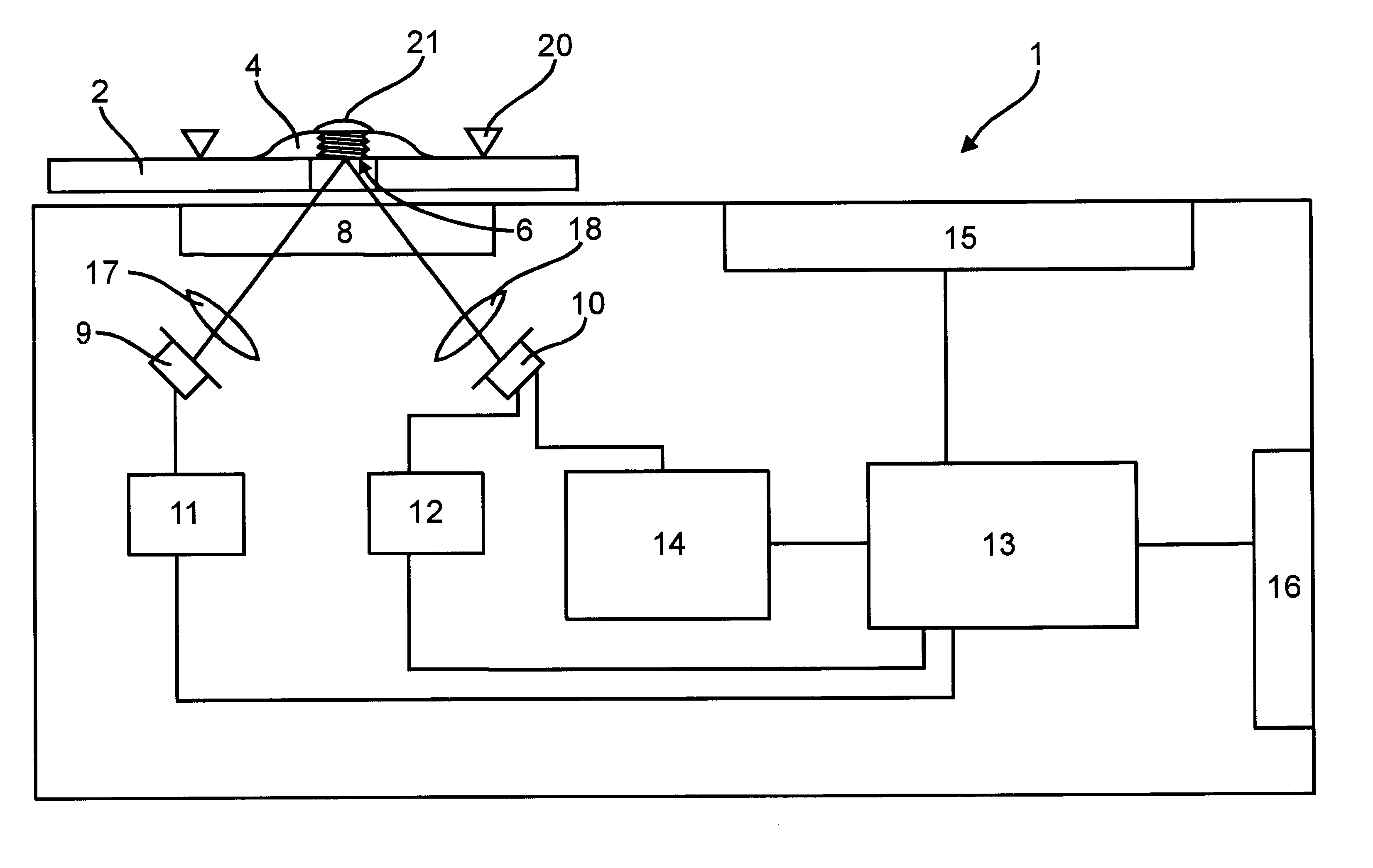
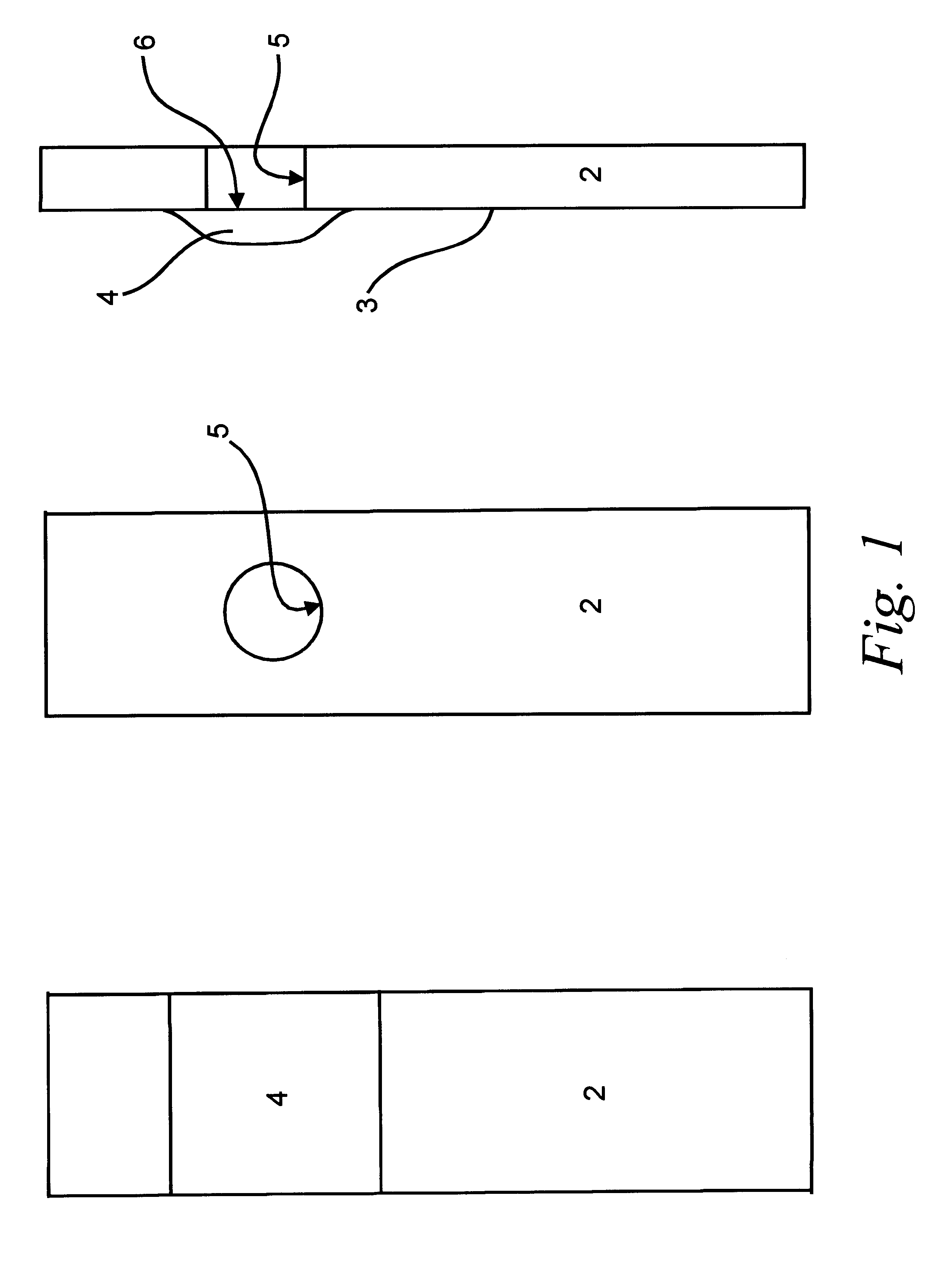
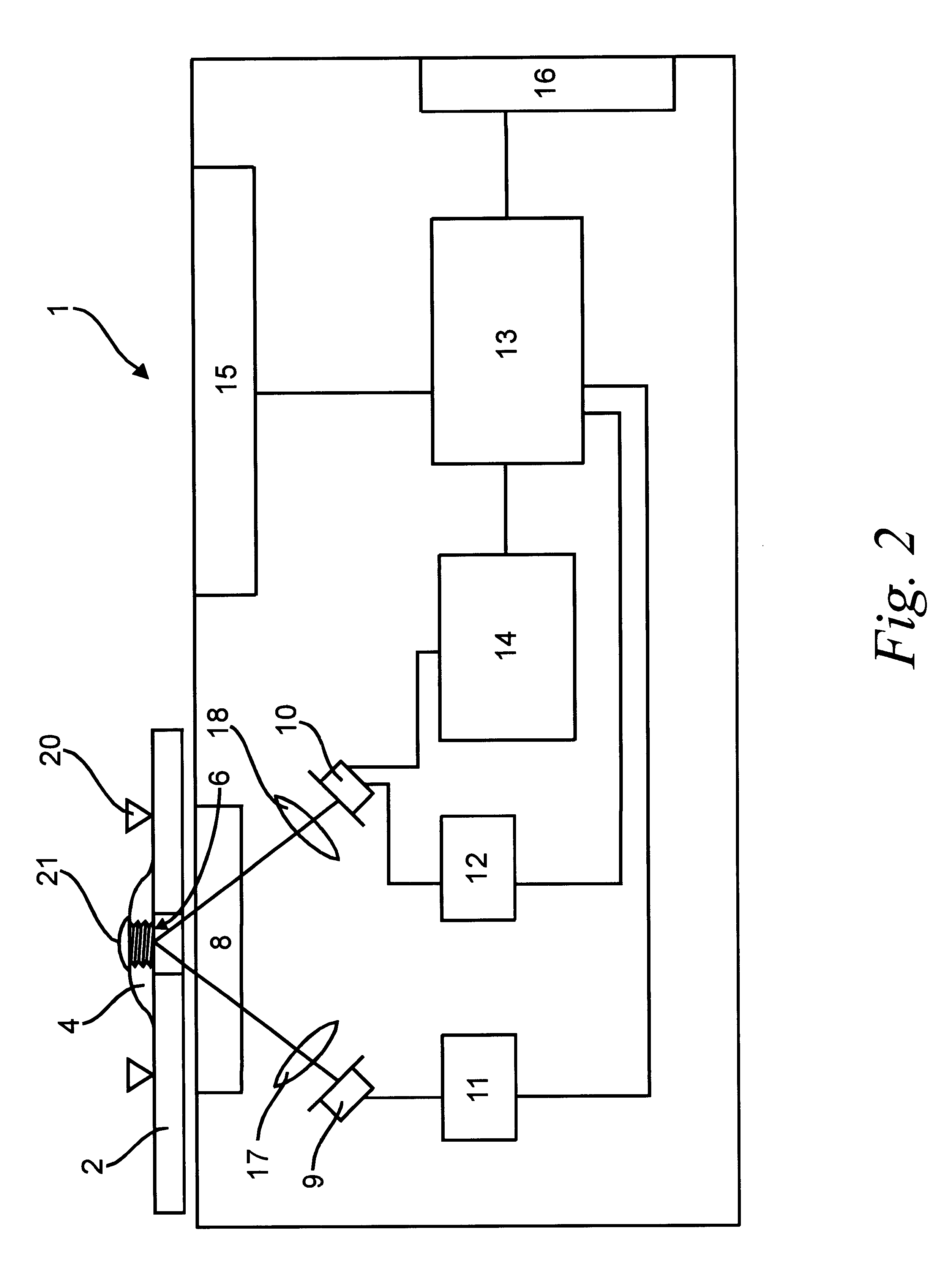
FIGS. 1 and 2 show the test strip 2 used in an embodiment of a method according to the present invention, and an embodiment of an apparatus 1 for performing the method according to the present invention. The test strip 2 involves a reagent entering into chemical reaction with the sample component to be determined. In the embodiment shown in FIGS. 1 and 2, the apparatus 1 is a blood glucose measuring device, which constitutes a blood glucose measurement system together with the known test strip 2, the latter is a known no-wipe type test strip. FIG. 1 shows different views of the test strip 2, from left to right: from the top, bottom and side. As is apparent from FIG. 1, on the top side 3 of the test strip 2 there is a 4 reagent matrix, also called a test pad, which contains the reagent entering into chemical reaction with the sample to be measured. The reagent matrix 4 is made of a textile or foil in a known manner. Below the reagent matrix 4 there is a hole 5 in the test strip 2. Th...


PUM

PropertyMeasurementUnit
wavelengthaaaaaaaaaa
refractive indexaaaaaaaaaa

Abstract

The invention relates to a method and apparatus for determining a chemical component from a sample, where the sample is measured on a test strip with the help of a color reaction. The method concerns finding the measurement time Tm for measuring the reflection of the test strip. The method comprises the following steps: a) Recording the R(t) function, b) Determining the T0 starting time at the detection of the wetting through of the sample, c) Generating the function R(t)+L(t), d) Monitoring and storing the ext[R(t)+L(t)] extreme value of the R(t)+L(t) function, and, at the same time, e) Generating the function R(t)+L(t)-ext[R(t)+L(t)] from the time of reaching an ext[R(t)+L(t)] extreme value, f) when the R(t)+L(t)-ext[R(t)+L(t)] function reaches a predetermined C(t) value, determining the Tm measuring time.

Description

FIELD OF THE PRESENT INVENTIONThe present invention relates to a method and apparatus for determining a chemical component from a sample of matter, in particular for determining the glucose content of blood from a blood sample.BACKGROUND OF THE PRESENT INVENTIONIt is generally known that diabetics are treating themselves in daily life. This is made possible by the use of domestic blood glucose measurement. In the known methods, patients with diabetes place a drop of blood on a test strip, which contains the reagent. The reagent will react with the glucose content of the blood, and generates a well-defined color. The reaction is a multi-stage reaction and is commonly known. The glucose-oxidase enzyme creates hydrogen-peroxide (H.sub.2 O.sub.2) from the glucose content of the blood, the oxygen of the air and of the water present in the blood. The amount of the H.sub.2 O.sub.2 generated is proportional to the amount of the glucose, and a peroxidase enzyme further activates it. The acti...

Claims


Application Information

Patent Timeline
Patent Type & Authority Patents(United States)
IPC IPC(8): G01N21/86
CPCG01N21/8483G01N2201/129
Inventor TAJNAFOI, GABOR
Owner 77 ELEKTRONIKA MUSZERIPARI
Learn More