
Fluid sterilization apparatus

a sterilization apparatus and flue technology, applied in the direction of multi-stage water/sewage treatment, other chemical processes, separation processes, etc., can solve the problems of pressure drop or head loss that occurs across the diffuser, the water treatment system or components thereof that function reliably and well in the home may not function at all well in a mobile working environment, and the pressure drop is relatively high

Inactive Publication Date: 2002-09-24
INT WATER GUARD INDS
View PDF10 Cites 20 Cited by
  • Summary
  • Abstract
  • Description
  • Claims
  • Application Information

AI Technical Summary

Benefits of technology

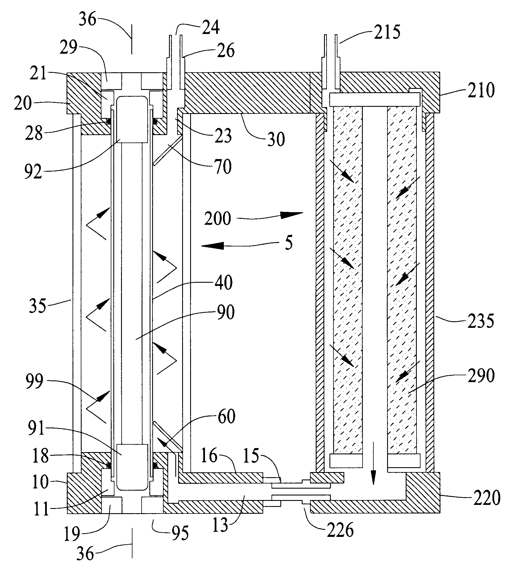
The input fluid flow guide or ramp is disposed within the annular chamber and extends longitudinally therein from the first end of the outer housing for a relatively short distance. Conversely, the output fluid flow guide or ramp, which is also disposed within the annular chamber but relatively far from the input flow guide or ramp, extends longitudinally from the second end of the outer housing for a relatively short distance.
In contrast to diffusers, baffles, or helical shaped guides that extend continuously for substantially the full length of an annular chamber, all of which may offer relatively high resistance to fluid flow and may present other disadvantages, the helical shaped guides as specified herein offer relatively low resistance. Yet, it has been found that they can serve to impart a significant and desirable spiral flow momentum to the fluid.

Problems solved by technology

A water treatment system or components thereof that function reliably and well in the home may not function at all well in a mobile working environment.
However, it has been found that the pressure drop or head loss that occurs across such diffusers is relatively high.
This can be disadvantageous if the fluid supply pressure is concurrently limited and it is desired to maintain a minimal water flow rate.
For a desired water flow rate through an ultraviolet sterilizer, such low pressures may preclude the use of a diffuser or, alternately, may preclude the use of other water treatment devices which themselves cause a pressure drop (e.g. a water filter) in the path of water flow.
While it may be remarked that the pressure drop induced by the fin described by Lewis is likely to be minimal, and while it may also be remarked that turbulence is desirable, it must also be remarked that Lewis' fin is not well adapted to induce a desirable spiral flow.
Thus, the water's exposure to ultraviolet radiation is undesirability limited.
However, it is noted that they specifically contemplate a high pressure home use environment, and it is anticipated that a significant pressure drop would occur, particularly across the baffle which may be compared with the diffuser of Free.
However, even assuming that ultraviolet transmissibility is normally adequate, there are disadvantages.
Firstly, there would be a relatively high pressure drop across the coil by reason of the added surface area presented by the surfaces of the coil over the length of the coil.
Secondly, it has to be recognized that sediment can build up on all surfaces over which water flows.
Sediment build up on the walls of the coil could very well impair the transmissibility of coil material that otherwise might demonstrate adequate ultraviolet transmissibility.
In contrast to diffusers, baffles, or helical shaped guides that extend continuously for substantially the full length of an annular chamber, all of which may offer relatively high resistance to fluid flow and may present other disadvantages, the helical shaped guides as specified herein offer relatively low resistance.

Method used


Image

  • Fluid sterilization apparatus
  • Fluid sterilization apparatus
  • Fluid sterilization apparatus

Examples


Embodiment Construction

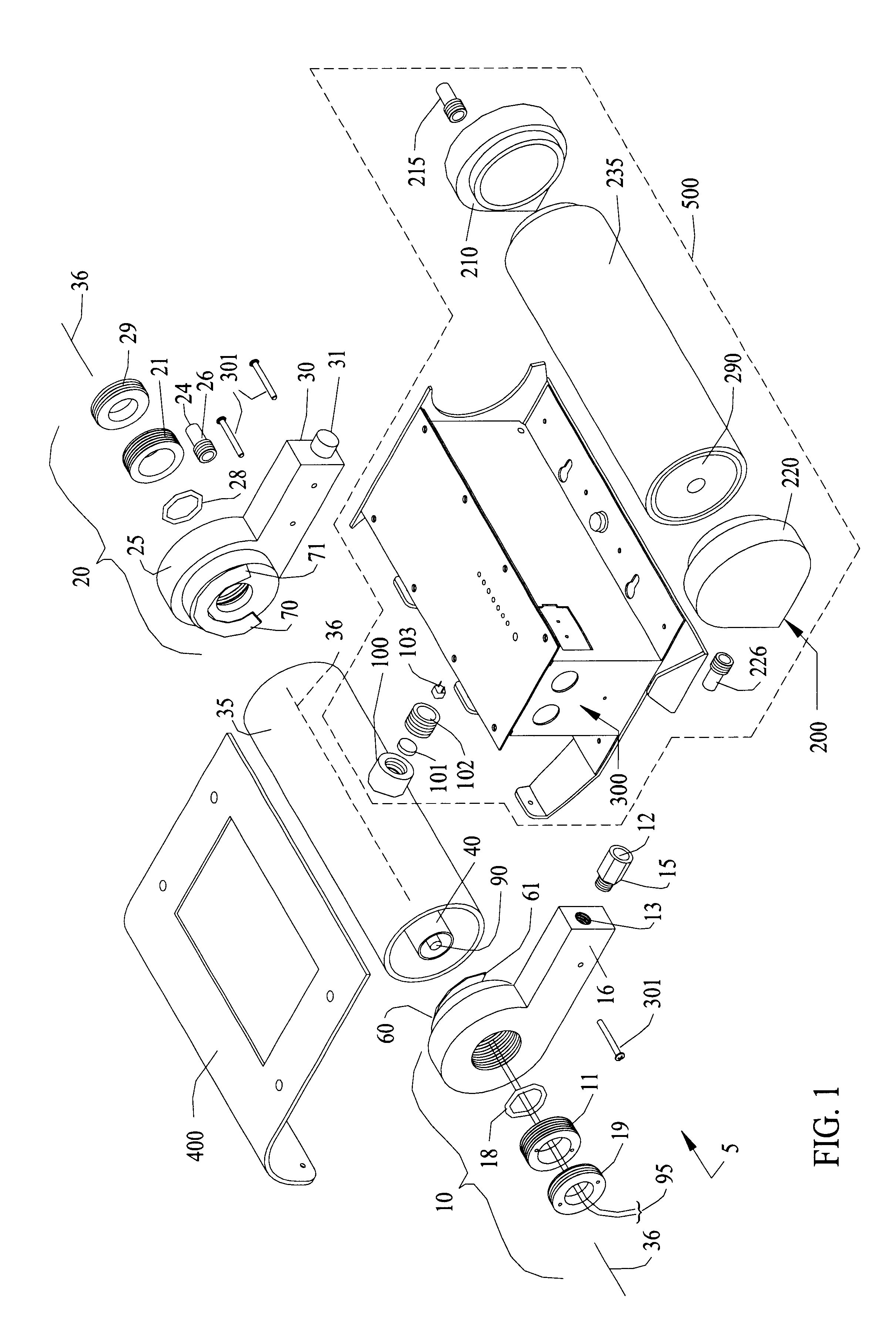
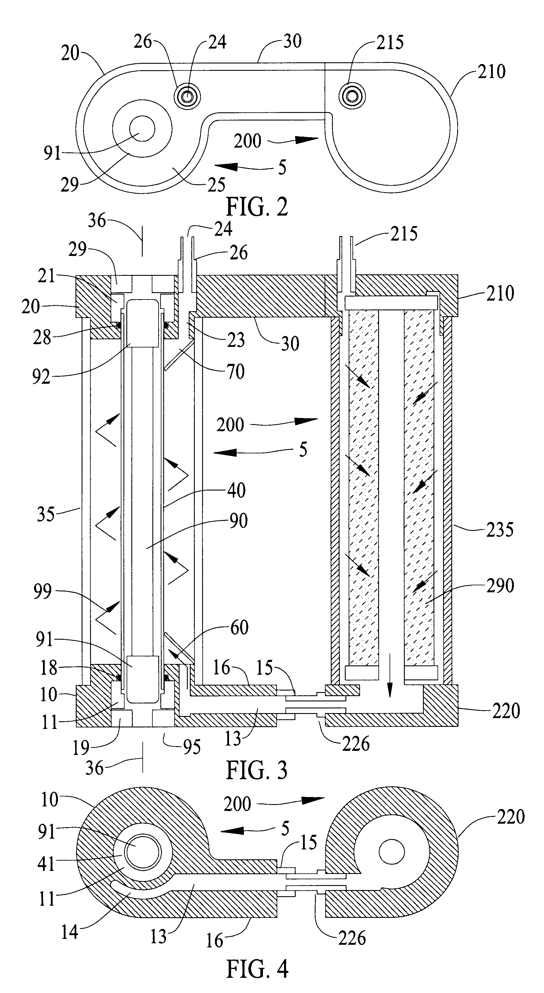
FIG. 1 illustrates a preferred embodiment of the present invention when configured to integrate with and form part of a potable water treatment system that includes not only apparatus generally designated 5 for treating water with radiant energy from an ultraviolet lamp, but also apparatus generally designated 200 for filtering such water before it is exposed to ultraviolet light. Further, the system as shown includes a housing assembly generally designated 300 to hold electrical and electronic components and circuitry for operating and monitoring the operation of the system. As well, the system includes a cover 400 which normally overlies lamp apparatus 5, filter apparatus 200, and housing assembly 300.

It is to be understood that cover 400 and generally that part of the system appearing within broken border 500, including filter apparatus 200 and housing assembly 300, is not considered to be part of the present invention. They are illustrated in the drawings only to better explain ...


PUM

PropertyMeasurementUnit
Momentumaaaaaaaaaa
Lengthaaaaaaaaaa
Timeaaaaaaaaaa

Abstract

Apparatus for treating water or other fluid with radiant energy from an ultraviolet lamp includes a helical shaped input fluid flow guide or helical ramp disposed at or near one end an elongated annular chamber around the lamp. The guide or ramp serves to impart input spiral flow momentum to the fluid upon entry to the chamber. A corresponding output fluid flow guide or helical ramp may be disposed at or near the opposed end of the chamber to impart output spiral flow momentum to the fluid as it approaches discharge from the chamber. Spiral flow serves to extend the time that the fluid is exposed to ultraviolet light and thereby increases the probability that any microbiological contaminants present in the fluid will be killed. The use of helical shaped guides or ramps better serves to establish such a flow in circumstances where the available fluid pressure is relatively low.

Description

This invention relates to fluid sterilization apparatus of the type for treating potable water or other fluids with radiant energy from an ultraviolet lamp.BACKGROUND TO THE INVENTIONIt is well known that the quality of potable water varies widely from city to city around the world. Indeed, the quality can vary significantly from place to place within a given city. To address this issue, numerous water treatment systems have been designed for domestic home use: A typical system may include a water filter for removing particulates and organic contaminants from the water, an ultraviolet lamp for irradiating the water with ultraviolet energy to kill contaminants in the water, a subsystem for operating and monitoring the operation of said system, and structures for housing such components. Often, such systems are designed to sit on a countertop in the user's home where they are connected to a public utility or other municipal water supply. For example, see U.S. Pat. No. 5,698,091 (Kuenn...

Claims


Application Information

Patent Timeline
IPC IPC(8): A61L2/10C02F9/00C02F1/32C02F1/00
CPCA61L2/10C02F1/325C02F9/005C02F2201/3223C02F2201/3228C02F2201/326C02F2301/024C02F2301/026C02F9/20
Inventor THORPE, GEORGE W.
Owner INT WATER GUARD INDS
Learn More