Method for preparing a lithographic printing plate by ablation of a heat sensitive ablatable imaging element

a technology of imaging element and lithographic printing plate, which is applied in the field of ablative imaging element preparation of lithographic printing plate, can solve the problems of cumbersome and laborious working method, insufficient sensitive photosensitive coating to be directly exposed to laser, above mentioned, etc., and achieve enhanced durability, enhanced differential in wettability, and enhanced reactive polymer properties

Inactive Publication Date: 2002-09-24
AGFA NV
View PDF21 Cites 19 Cited by
  • Summary
  • Abstract
  • Description
  • Claims
  • Application Information

AI Technical Summary

Benefits of technology

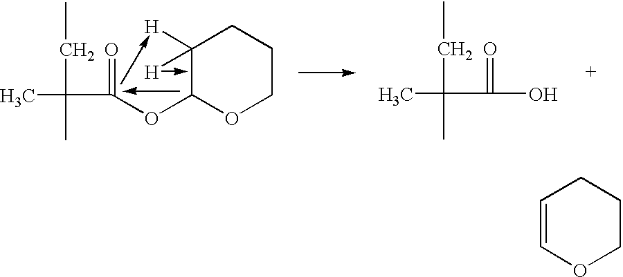
The process is greatly enhanced by the presence of acid, and enables the production of a lithographic printing surface without the need of dissolution development, since image-wise generation of heat and / or acid within the coating of a relevant polymer produces a corresponding pattern of hydrophilic (ink-repellent) and hydrophobic (ink-accepting) areas on the imaging element.
The properties of the reactive polymer may be enhanced by blending with other polymers, as disclosed in WO 92 / 09934. Polymers and copolymers of maleic anhydride are particularly suitable for this purpose, and may comprise up to 90 wt % of the coating, but preferably not more than 50 wt %. the resulting blends show improved durability and enhanced differential in wettability.

Problems solved by technology

Lithography is the process of printing from specially prepared surfaces, some areas of which are capable of accepting lithographic ink, whereas other areas, when moistened with water, will not accept the ink.
Such method of working is cumbersome and labor intensive.
However the above mentioned photosensitive coatings are not sensitive enough to be directly exposed to a laser.
Such method is disclosed in for example JP-A- 60- 61 752 but has the disadvantage that a complex development and associated developing liquids are needed.
This method however still has the disadvantage that the image mask has to be removed prior to development of the photosensitive layer by a cumbersome processing.
A particular disadvantage of photosensitive imaging elements such as described above for making a printing plate is that they have to be shielded from the light.
Furthermore they have a problem of sensitivity in view of the storage stability and they show a lower dot crispness.
So far, none has proved commercially viable and all require wet development to wash off the unexposed regions.
This method has the disadvantage that in said way it is very difficult to generate a fog-free aluminum support.
Plates made by ablation can not be printed without scumming.
This principle has as disadvantage that the lithographic latitude is very narrow whereby pretty fast toning occurs at the exposed areas.

Method used


Image

  • Method for preparing a lithographic printing plate by ablation of a heat sensitive ablatable imaging element
  • Method for preparing a lithographic printing plate by ablation of a heat sensitive ablatable imaging element
  • Method for preparing a lithographic printing plate by ablation of a heat sensitive ablatable imaging element

Examples


Embodiment Construction

1

An imaging element I was prepared by coating a 180 .mu.m thick aluminum sheet, having a grained and anodized surface, with a solution of a switchable copolymer (tetrahydropyranyl methacrylate / methacryloxypropyl-trimethoxysilane) in a monomer ratio of 90 / 10 by mol (0.35 g), and an IR-absorbing dye IR-1 (0.0365 g) in methyl ethyl ketone resulting in a themosensitive layer with a dry layer thickness of 1.8 g / m.sup.2. The optical density was 0.49. As a reference imaging element II was prepared with a heat-sensitive layer as imaging element I except that the switchable polymer was replaced by a novolac binder Alnovol SPN452.TM., sold by Clariant, Germany. The optical density was 0.25.

The plates were exposed on an ISOMET testbed equiped with a diode laser (830 nm) having a laser spot of 11.times.11 .mu.m.sup.2 at the 1 / e.sup.2 point. The plates were exposed at different image plane power settings at a drum speed of 3.2 m / s. The optical densities of the exposed areas were measured (Macbet...


PUM

PropertyMeasurementUnit
mol %aaaaaaaaaa
mol %aaaaaaaaaa
optical densityaaaaaaaaaa

Abstract

According to the present invention there is provided a method for preparing a lithographic printing plate, the method including the steps of(1) providing an imaging element including on a lithographic hydrophilic support as contiguous top layer a heat-sensitive coating including a compound capable of converting light to heat and a compound, which becomes more hydrophilic under the action of heat;(2) imagewise exposing the imaging heat-sensitive composition with a high intensity laser emitting a laser beam with an intensity at the surface of the heat-sensitive composition of tat least 2 mW/mum2 thereby at least partially removing the heat-sensitive composition to expose at least partially the lithographic support.

Description

The present invention relates to a heat sensitive ablatable imaging element.More specifically the invention is related to a heat sensitive ablatable imaging element for preparing a lithographic printing plate, which requires no dissolution processing.Lithography is the process of printing from specially prepared surfaces, some areas of which are capable of accepting lithographic ink, whereas other areas, when moistened with water, will not accept the ink. The areas which accept ink define the printing image areas and the ink-rejecting areas define the background areas.In the art of photolithography, a photographic material is made imagewise receptive to oily or greasy inks in the photo-exposed (negative working) or in the non-exposed areas (positive working) on a hydrophilic background.In the production of common lithographic printing plates, also called surface litho plates or planographic printing plates, a support that has affinity to water or obtains such affinity by chemical tr...

Claims


Application Information

Patent Timeline
Patent Type & Authority Patents(United States)
IPC IPC(8): B41C1/10
CPCB41C1/1033Y10S430/146Y10S430/145Y10S430/165
Inventor DAMME, MARC VANHENDRIKX, PETER
Owner AGFA NV
Why Eureka
Try Eureka