PFC apparatus for a converter operating in the borderline conduction mode

a technology of conduction mode and converter, which is applied in the direction of electric variable regulation, process and machine control, instruments, etc., can solve the problems of low power transmission efficiency, possible interference with other units connected to the power line, and distortion of the line voltage shap

Inactive Publication Date: 2002-10-22
GREEN POWER TECH LTD
View PDF13 Cites 154 Cited by
  • Summary
  • Abstract
  • Description
  • Claims
  • Application Information

AI Technical Summary

Benefits of technology

Preferably, the control circuit comprises: a) a first means for digitizing the output voltage of the converter; b) a second means for digitizing the input current of the converter; and c) means for processing the data gathered from the first and second digitizing means, for generating the switching signal for the first controllable switch.
The control circuit components may be contained in a module that comprises five external contacts or in an integrated circuit (IC). The input current sensing resistor and / or the output diode and / or the power switch may be contained in, or being external to, a module that comprises five external contacts and / or to an integrated circuit (IC).

Problems solved by technology

Injection of high harmonics into the power line and poor Power Factor (PF) in general, is known to cause many problems.
Among these problems are the lower efficiency of power transmission, possible interference to other units connected to the power line, and distortion of the line voltage shape.
Consequently, the rms current limits the maximum power that can be drawn from the line.
Cost is of great concern, considering the fact that the APFC is an add-on expense to the functionality of the original equipment in which the APFC converter is included.
However, reverse recovery of the main diode D.sub.2 poses extra losses and EMI generation.
Furthermore, implementing an APFC converter in CCM mode requires that L.sub.in is of high inductance value, making it bulky and costly.
The DCM is the least desirable since the inductor rms current is the highest, which increases the power switch losses and makes the main inductor large in size, because the physical size of an inductor is proportional to the rms current that is expected to pass through it.
A major drawback of the prior art BCM converter is the need to sense the converter s input voltage, namely the line voltage after rectification.
Due to the switching effects, the input voltage V.sub.ivR is normally noisy and is susceptible to interference that may distort the reference signal and hence the controlled input current.
Furthermore, the extra contact required for sensing the input current increases the number of pins of a modular device, if built according to conventional BCM schemes.
However, conventional methods that do not sample the input voltage cannot operate in the BCM, but only in CCM and, with some inferior performance, in DCM.
Consequently, APFC control schemnes that apply constant switching frequency cannot operate as BCM APFC controllers.
However, this disclosure suffers from the same drawback as U.S. Pat. No. 5,742,151.
As it is known in the art, differentiators are extremely sensitive to noise that may corrupt the output signal.
Another drawback of the solution of said patent is that the reference feedback signal is derived from the line voltage.
Since this signal normally includes noise, the derived reference signal may be highly corrupted by signals that distort the shape of the desired controlled line current.
High cost and low reliability are normally associated with a design that includes a large component count.
Furthermore, as known in the art, the rather massive wiring required to realize the APFC converter makes it highly susceptible to Electro Magnetic Interference (EMI) and `ground` noises.
Consequently, this embodiment is highly undesirable, as it has many economic and engineering drawbacks; 2. Another possible embodiment of the APFC converter is to implement it as one block that includes all major components.
However, a problem of heat removal arises in this case.
Additionally, being a separate unit that is normally obtained from a third party, the cost of such a solution is normally high.
Another disadvantage of this approach is the fact that it is compatible with IC technology and hence cannot benefit from the relatively low production cost of microelectronics.
A further drawback of the one-block construction is the fact that all heat dissipating components, such as the main switch, diodes and inductor, are in close proximity to each other and hence the problem of heat removal could limit the ability of such a module to handle high power levels.
Also, close proximity components that generate considerable EMI necessitates the inclusion of heavy shielding and filtering that increase complexity and cost and lower the efficiency.
All of the methods described above have not yet provided solutions to the problem of utilizing BCM-based APFC circuits without sampling the AC line voltage or the voltage at the APFC converter input.

Method used


Image

  • PFC apparatus for a converter operating in the borderline conduction mode
  • PFC apparatus for a converter operating in the borderline conduction mode
  • PFC apparatus for a converter operating in the borderline conduction mode

Examples


Embodiment Construction

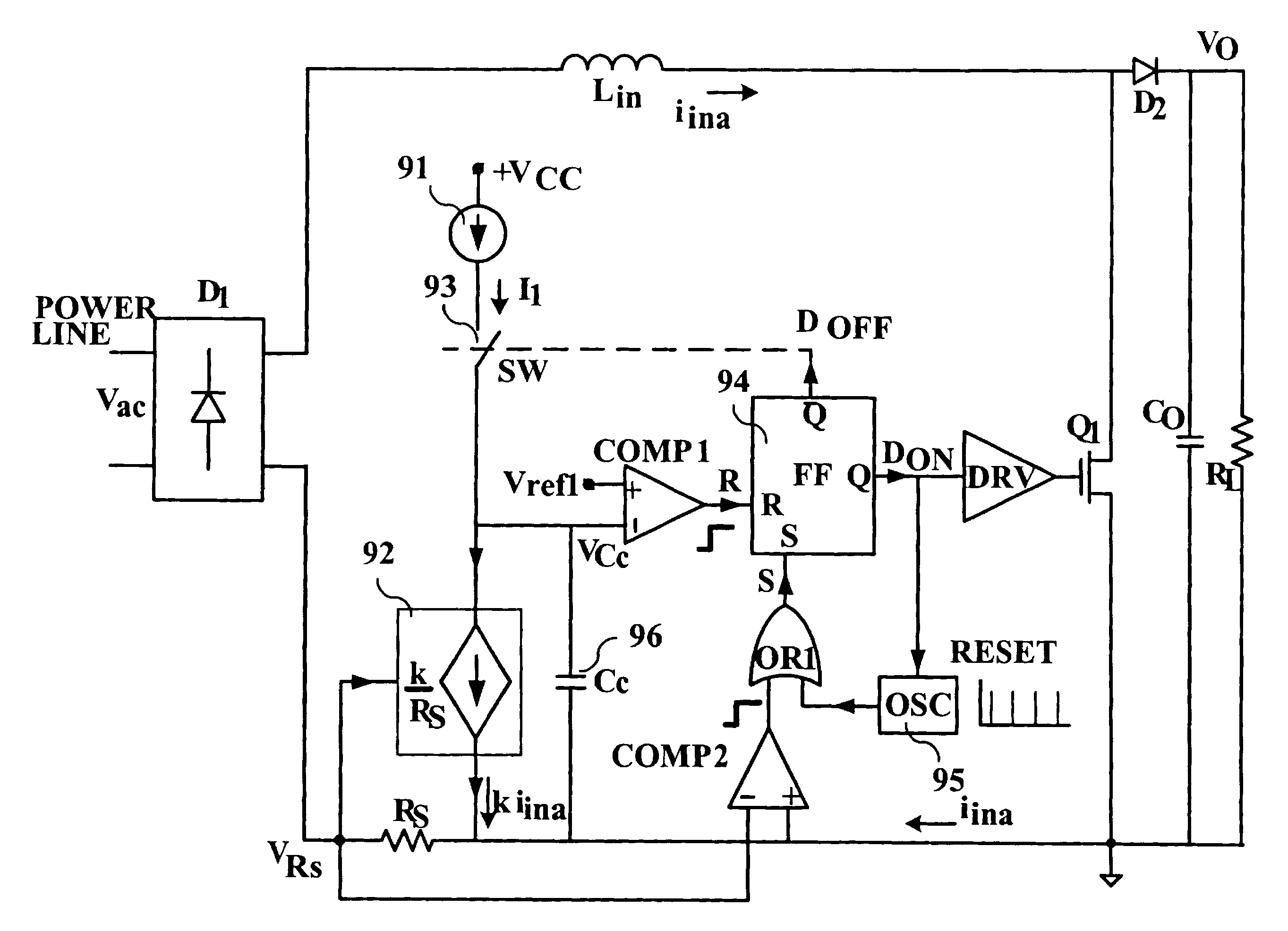
In one aspect, the present invention relates to a method for realizing an APFC converter that forces the system to remain in the Borderline Conduction Mode (BCM) without sampling the voltage at the input of the converter. With a small adaptation, the novel control methods can also be utilized for APFC operating in CCM mode.

Two current sources are utilized for charging a capacitor for a first duration being equal to "T.sub.OFF ", and for discharging the same capacitor for a second duration being equal to "T.sub.ON ". The capacitor may be either in a state of `charging` or in a state of `discharging`. For current sources having constant magnitudes, "T.sub.OFF " depends only on the time it takes the inductor current to reach zero. On the other hand, the longer the duration "T.sub.OFF " is, the higher the voltage level of the capacitor, resulting in longer "T.sub.ON ", since it takes the capacitor more time to discharge. Consequently, different loads have different "T.sub.ON " and "T.su...


PUM


Abstract

Power factor correction apparatus, for a switching power supply fed by an array of rectifying diodes and consisting of at least an input inductor, a contact of which is connected in series with a contact of the array, and of a power switch connected between the other contact of the array and the other contact of the input inductor that comprises circuitry for identifying, in each cycle determined by the switching frequency of the power supply, whenever the instantaneous value of the current through the inductor reaches a minimal value; circuitry for switching the power switch to its conducting state in response to the minimal current through the inductor; circuitry for reflecting the current flowing through the inductor by a measurable or simulated parameter; and circuitry for providing indication, in each cycle, by using the parameter, the indication being related to the timing until the peak value of the current, that corresponds to a specific load, has been essentially reached, or to the time from the moment that the current reaches the minimal value until the timing, and for switching the power switch to its non-conducting state in response to the indication.

Description

FIELD OF THE INVENTIONThe present invention relates to the field of switching power converters. More particularly, the present invention relates to a method and apparatus for regulating the harmonics content of the current drawn from the power line boy electrical equipment and loads by utilizing Borderline Conduction Mode (BCD) of operation without sampling the input voltage. The present invention also relates to the electronic circuit design, physical construction and layout of such an apparatus.BACKGROUND OF THE INVENTIONCurrently, there are several types of converters, which are widely used for DC-to-DC, DC-to-AC, AC-to-DC and AC-to-AC power conversion. In some applications, the purpose of the power conversion schemes is to shape the input current seen at the input of the converter, in order to correct the power factor. For example, in a power converter known in the art as an Active Power Factor Correction (APFC) converter, the role of the converter is to ensure that the AC curre...

Claims


Application Information

Patent Timeline
Patent Type & Authority Patents(United States)
IPC IPC(8): H02M1/00H02M1/42
CPCH02M1/4225Y02B70/126Y02B70/10Y02P80/10
Inventor BEN-YAAKOV, SHMUEL
Owner GREEN POWER TECH LTD
Why Eureka
Try Eureka