Cutting metal alloy for shaping by electrical discharge machining methods

a technology of electrical discharge and metal alloy, applied in the field of cutting metal alloy, can solve the problems of limited application of cobalt-rhenium binder, lower hardness, and lower toughness of abrasives,

Inactive Publication Date: 2003-02-04
PLANSEE TIZIT
View PDF2 Cites 39 Cited by
  • Summary
  • Abstract
  • Description
  • Claims
  • Application Information

AI Technical Summary

Benefits of technology

Accordingly, it is an object of the present invention to provide a cutting metal alloy which is manufactured, as before, on a WC--Co basis because of the severe requirements for the combination of abrasive wear resistance, toughness, and hardness, and which is more suitable for electrical discharge processing than the WC--Co cutting metal types used to now.

Problems solved by technology

However, the former, as a rule, have a lower degree of hardness and as a result, lower abrasive wear and toughness characteristics.
Whereas hitherto known additives to the cobalt binder reacted with the carbide phase, with the formation of brittle, complex carbides and thus compensated negatively for any quality improvement of the binder phase, this limitation does not apply to the cobalt-rhenium binder.
Cutting metals of WC--Co, used to now for shaping by means of electrical discharge processing, exhibit, as a serious disadvantage, a phenomenon, which is frequently designated in technical circles as "pitting"--that is, holes with a depth of up to 20 .mu.m appear in the workpiece surface in components manufactured by means of erosion, with a probability of approximately 1 to 5% in statistically irregular individual cases.
This corrosive dissolution process can be the direct consequence of an insufficient rinsing of the cutting gap between the workpiece and the eroding electrode with the liquid dielectric, which brings about an increase in the electrical conductance there, or an excessively high conductance of the dielectric.
Frequently, the cobalt dissolution cannot be seen without a microscope, since the surface appears to be in an optically satisfactory condition prior to removal of the carbide phase.
With complex-dimensioned cutting profiles and with demanding manufacturing parameters, however, a sufficient rinsing of the cutting gap cannot be ensured up to now and "pitting" can, therefore, not be ruled out.
Rather, the known countermeasures are limited to the publication of "Points of departure for solving the problem of pitting," such as: "Note, constantly, the conductance of the dielectric and maintain smaller than 5 .mu.m S / cm" or "Interrupt the processing or do not start it at all, if the aforementioned conductance can be maintained only with a lot of effort."
The practical result is an unsatisfactory number of rejects of eroded cutting metal workpieces.

Method used


Image

  • Cutting metal alloy for shaping by electrical discharge machining methods
  • Cutting metal alloy for shaping by electrical discharge machining methods

Examples


example 2

The powder batch had the following composition in accordance with the invention: 12 wt % Co; 0.1 wt % Ge; 0.2 wt % TiC; 0.4 [wt %] Ta / NbC; remainder WC.

The production process for the fabrication of the cutting metal sample and the physical-mechanical characteristics determined on the sample corresponded to those of Example 1 and at the same time, to those of the ISO type K40. The electrochemical corrosion studies were carried out as described before Example 1.

The following values were produced:
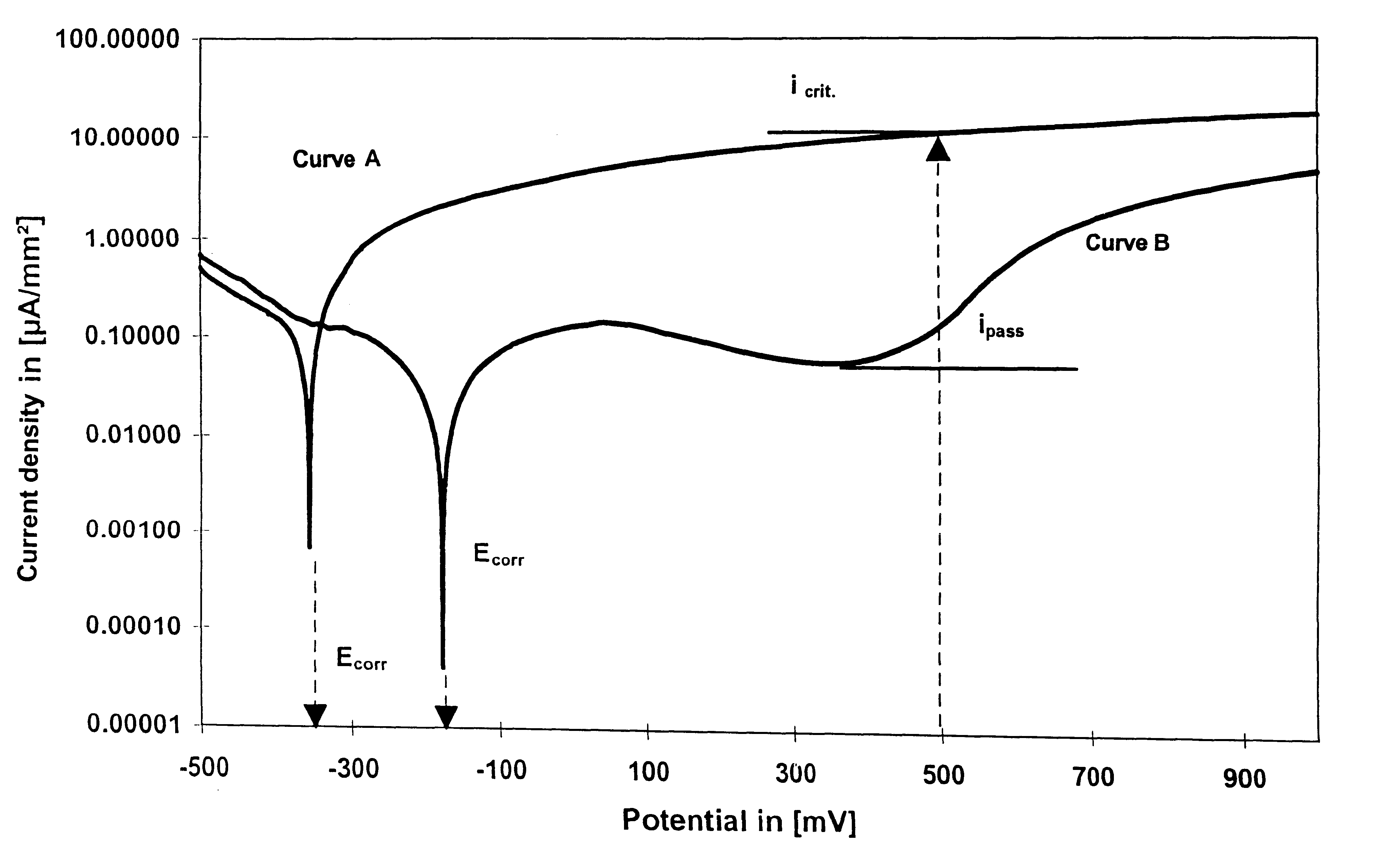
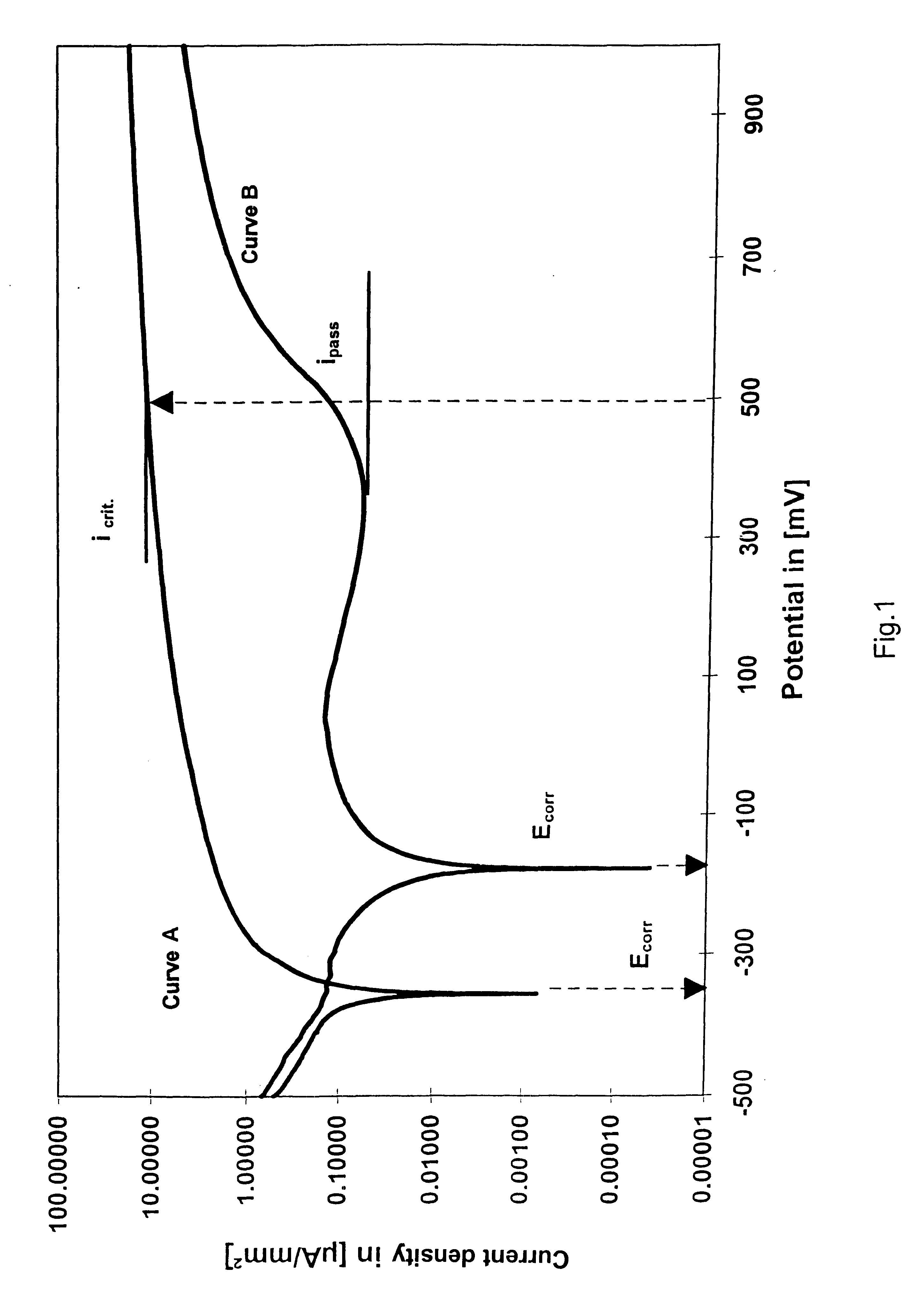
Curve type: "A"

E.sub.corr (mV)=-288

i.sub.crit (.mu.A / mm.sup.2)=8.021

A comparison with the standard type K40 showed that the cutting metal according to this example also exhibited clearly more favorable corrosion values and notwithstanding, produced comparably good cutting results and service lives for punching tools produced by means of electrical discharge machining methods.

example 3

Example 3 was used for the determination of E.sub.corr, I.sub.pass characteristics for a cutting metal type which differs from the sta ndard K40 in that chromium was added to it, which suddenly makes this cutting metal alloy more corrosion-resistant, in comparison to a pure K40.

The powder composition used was, accordingly, the following: 12 wt % Co, 0.8 wt % Cr.sub.3 C.sub.2, remainder WC.

The characteristics thus obtained were used as a reference for Examples 4-7 below, in accordance with the invention, in which components essential to the invention were also added to a powder batch analogous to this Example 3.

By means of a microprobe measurement, it was determined that the Cr.sub.3 C.sub.2 added to the powder batch had decomposed during the sintering and that the Cr fractions were completely dissolved in the Co binding phase.

The electrochemical investigations corresponded to the description given above and produced the following:

Curve type: "B"

E.sub.corr (mV)=-247

i.sub.pass (.mu.A / ...

example 4

The powder selection and cutting metal production were carried out as described before Example 1; the chemical composition of the powder batch was as follows: 12% Co; 0.8% Cr.sub.3 C.sub.2 ; 500 wt-ppm Re; remainder WC.

The physical and mechanical characteristics agreed with those according to Example 1.

With the electrochemical current density potential measurement (carried out as described before Example 1), the following results were obtained:

Curve type B

E.sub.corr (mV)=-196.7

i.sub.pass (.mu.A / mm.sup.2)=0.0461

The addition of Re to an otherwise standard powder batch according to Example 3 brought about a sudden improvement in the coefficients E.sub.corr and i.sub.pass, in comparison to the values determined there.

From two sintered cutting metal blocks (dimensions: 150.times.80.times.45 mm), 40 punching rams for a rotor-stator tool were produced to finished dimensions, without any signs of a corrosive attack--under standard conditions specified by the unit manufacturer for an "AGIE E...


PUM

PropertyMeasurementUnit
diameteraaaaaaaaaa
grain sizeaaaaaaaaaa
depthaaaaaaaaaa

Abstract

The invention concerns the use of a WC-Co cutting metal alloy for a component or a tool insert, which is shaped from a corresponding cutting metal blank by means of an electrical discharge processing method. The WC fraction in the carbide phase of the cutting metal alloy is more than 90 wt %; the binder phase consists mostly of cobalt and is 8 to 15 wt % with reference to the cutting metal alloy. 0.1 to 3 wt % of one or more metals from the group Re, Ge, Ga, Ir, Os, Pd, Ag, Au, Pt, Te, Sb, Rh, and Ru, with reference to the binder phase, are dissolved in the binder phase.

Description

The present invention concerns the use of a tungsten-cobalt cutting metal alloys as components shaped from cutting metal blanks by means of electrical discharge machining methods. These alloys can be used for cutting and punching tools having a complex configuration, which are shaped by wire eroding or cavity sinking.A large number of different cutting metal types, used, e.g. as dies in machining tools, are being employed to an increasing extent as materials for wear-resistant components or structural parts, for example, in the manufacture of tools.The cutting or shaping of workpieces by electrical discharge machining was developed in the 50s for the processing of steel materials and is used today, more and more, for the shaping of workpieces made of cutting metal. The production of geometrically complex molded articles by electrical discharge machining methods is clearly more economical, for comparable quality, than the usual compression molding and the subsequent metal cutting.The...

Claims


Application Information

Patent Timeline
Patent Type & Authority Patents(United States)
IPC IPC(8): B23H9/08B23H9/00C22C29/08C22C29/06
CPCC22C29/08B23H9/08B23H9/00B22F2005/001
Inventor LACKNER, ANDREASFERSTL, WERNERKNUNZ, GERHARDMARTINZ, HANS-PETERPRANDINI, KLAUS
Owner PLANSEE TIZIT
Why Eureka
Try Eureka