
Ultrasound transceiver system for remote operation through a minimal number of connecting wires

Inactive Publication Date: 2003-04-01
PREXION
View PDF2 Cites 92 Cited by
  • Summary
  • Abstract
  • Description
  • Claims
  • Application Information

AI Technical Summary

Benefits of technology

In a simpler implementation, the invention achieves steered focus and aperture with a two wire cable between the imaging instrument and the transducer system by using a pre-programmed amplifier and switching circuit. The switching circuit selectively combines a set of pre-focused array elements with preset delays, for each focal range. The preset focus and delay for each element is selected so that the phase error both across each element and across the active aperture, is less than a limit, say 90-120 deg, for the range the element participates to the beam forming. Combining an increasing number of elements with depth, one obtains an increasing aperture that limits the beam diameter with the increasing depth.
In a particularly simple implementation, both the pre focusing and delay of each element are provided with acoustic lens material with adapted curvature and thickness in front of each element. The electronic circuit then provides possible amplification of the signal from each element before the signals are selectively added in a time steered switching circuit that is reset by the pulse transmission.

Problems solved by technology

However, the image depth with ultrasound echo imaging is limited by absorption of ultrasound energy in the tissue.
The image resolution is therefore limited by the image depth.
For imaging of small structures like the vessel wall, or other small structures of internal organs, it is therefore necessary to bring the ultrasound transducer close to the structure, so that the image depth, and hence the absorption attenuation of the ultrasound, is limited.
1. With ultrasound frequencies above 30 MHz, impedance mismatch between the transducer and the cable connecting to the imaging instrument introduces losses that limits the signal to noise ratio and hence the maximal image depth at a given frequency. The limited thickness of the insertion instrument also limits the thickness of the wires that connects the transducer and the imaging instrument giving additional absorption and reduced imaging sensitivity.
2. At for example 35 MHz, the electromagnetic wavelength in the cable is .about.6 m, giving a quarter wavelength of .about.1.5 m that is approximately the length of a typical catheter. The catheter hence becomes similar to a quarter wave tuned antenna in the ultrasound receiver frequency range, and the imaging system becomes very sensitive to external electromagnetic interference (EMI) sources in the active receiver frequency range.
3. Other problems in using a thin cable between the ultrasound transducer and the instrument is related to obtaining narrow ultrasound beams. To reduce the effect of ultrasound wave diffraction in the beam focus, and hence reduce the focal diameter, one must have a large number of wavelengths across the active transducer aperture (typically .about.50 wavelengths across the aperture are wanted). However, with such low diffraction focusing, the depth of the focus is reduced, limiting the range of sharp focusing and spatial resolution.

Method used


Image

  • Ultrasound transceiver system for remote operation through a minimal number of connecting wires
  • Ultrasound transceiver system for remote operation through a minimal number of connecting wires
  • Ultrasound transceiver system for remote operation through a minimal number of connecting wires

Examples


Embodiment Construction

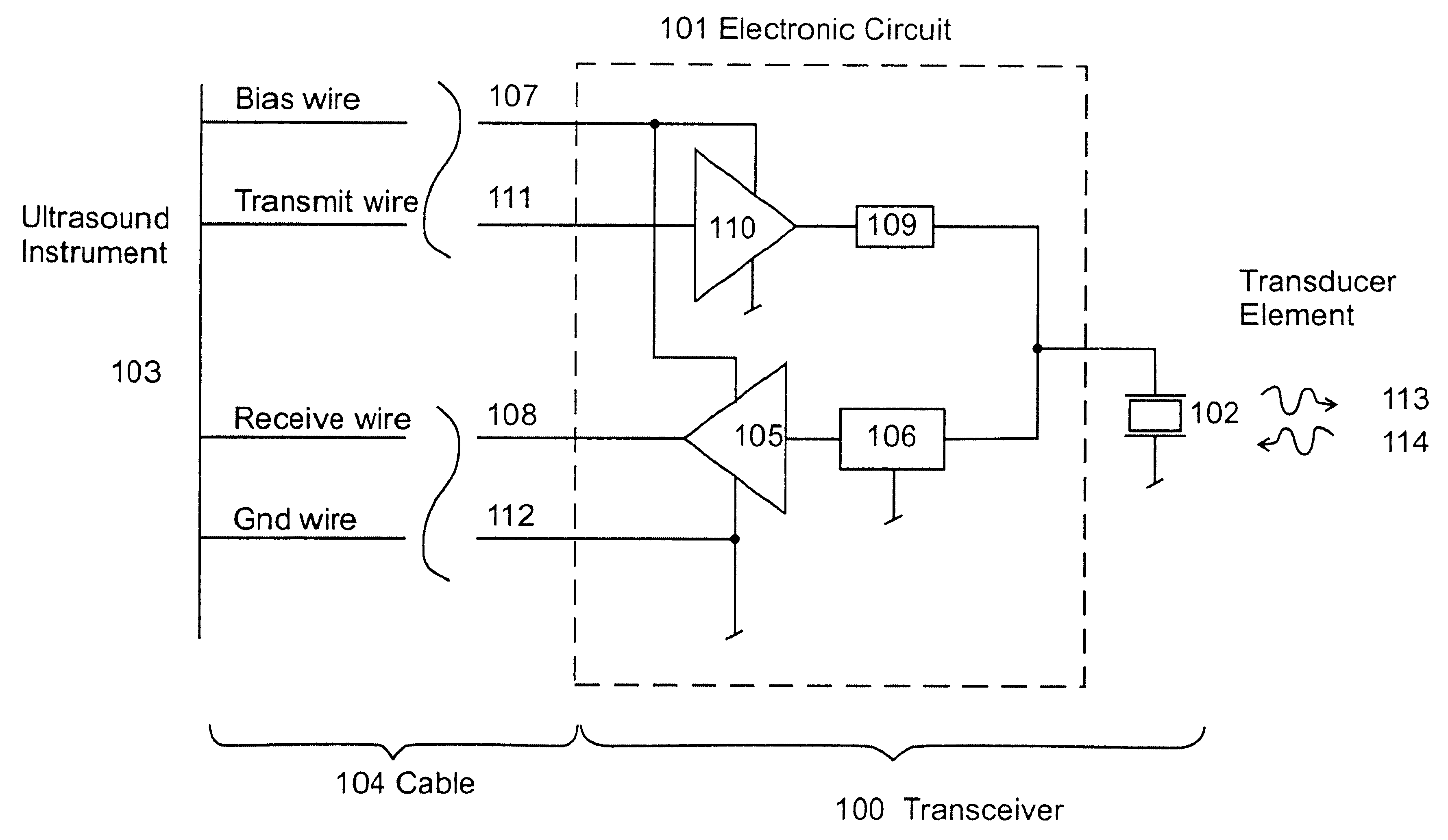
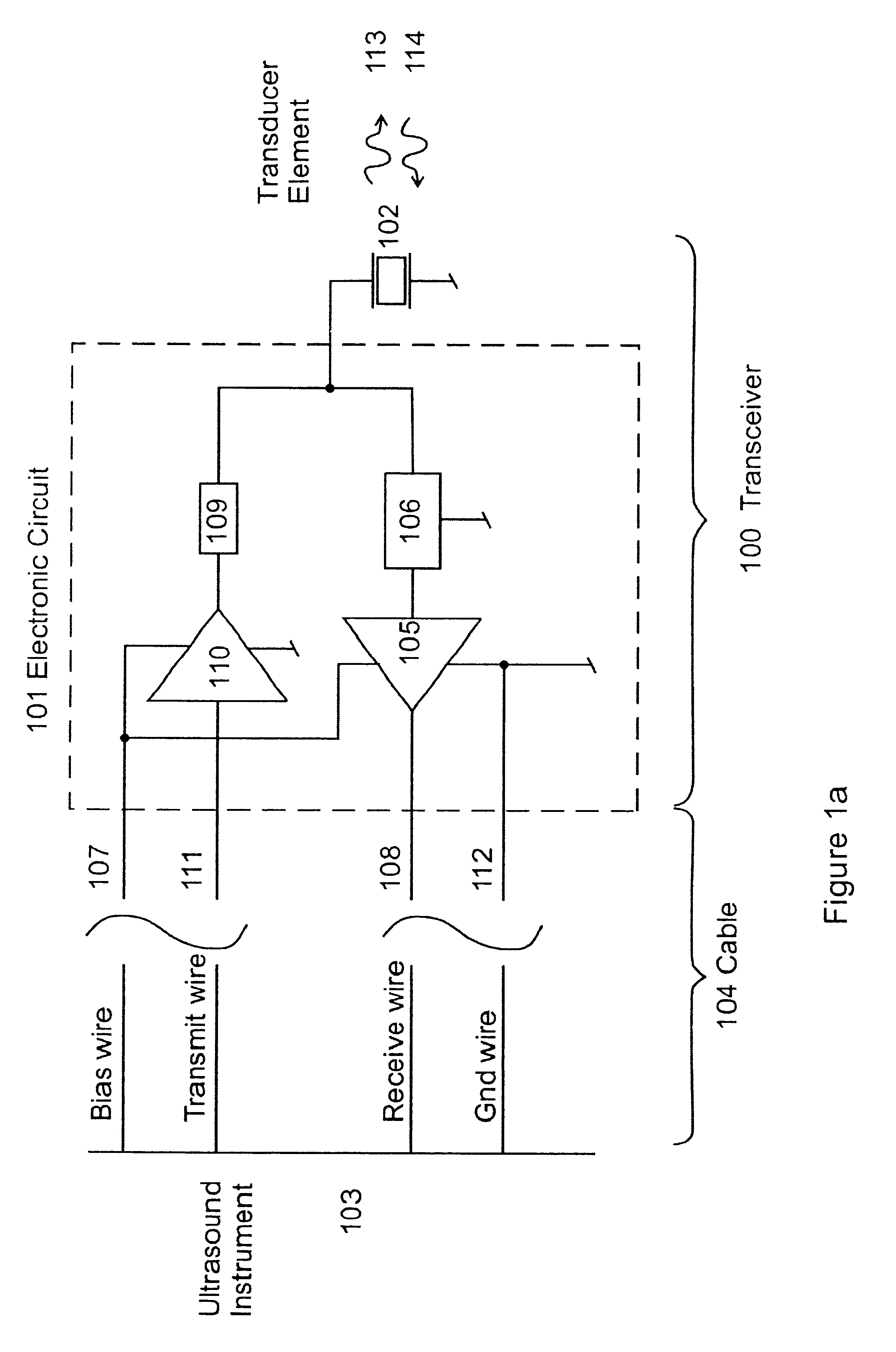
Several examples of embodiments of the invention are presented in the following, with reference to the Figures. FIG. 1a shows an ultrasound pulse echo transceiver unit 100, composed of an electronic circuit 101 and an ultrasound transducer 102. The transceiver unit is coupled to an ultrasound measurement or imaging instrument 103 via a multi wire cable 104. The DC-bias voltage to the electronic circuit is fed from the ultrasound instrument via a bias wire 107, and the transceiver has a common ground connected to the ultrasound instrument via a gnd wire 112. It is clear also that according to common techniques of shielding of low level receive signals from external electromagnetic interference, the whole cable can be enclosed in a conducting metal shield that is grounded at the instrument.

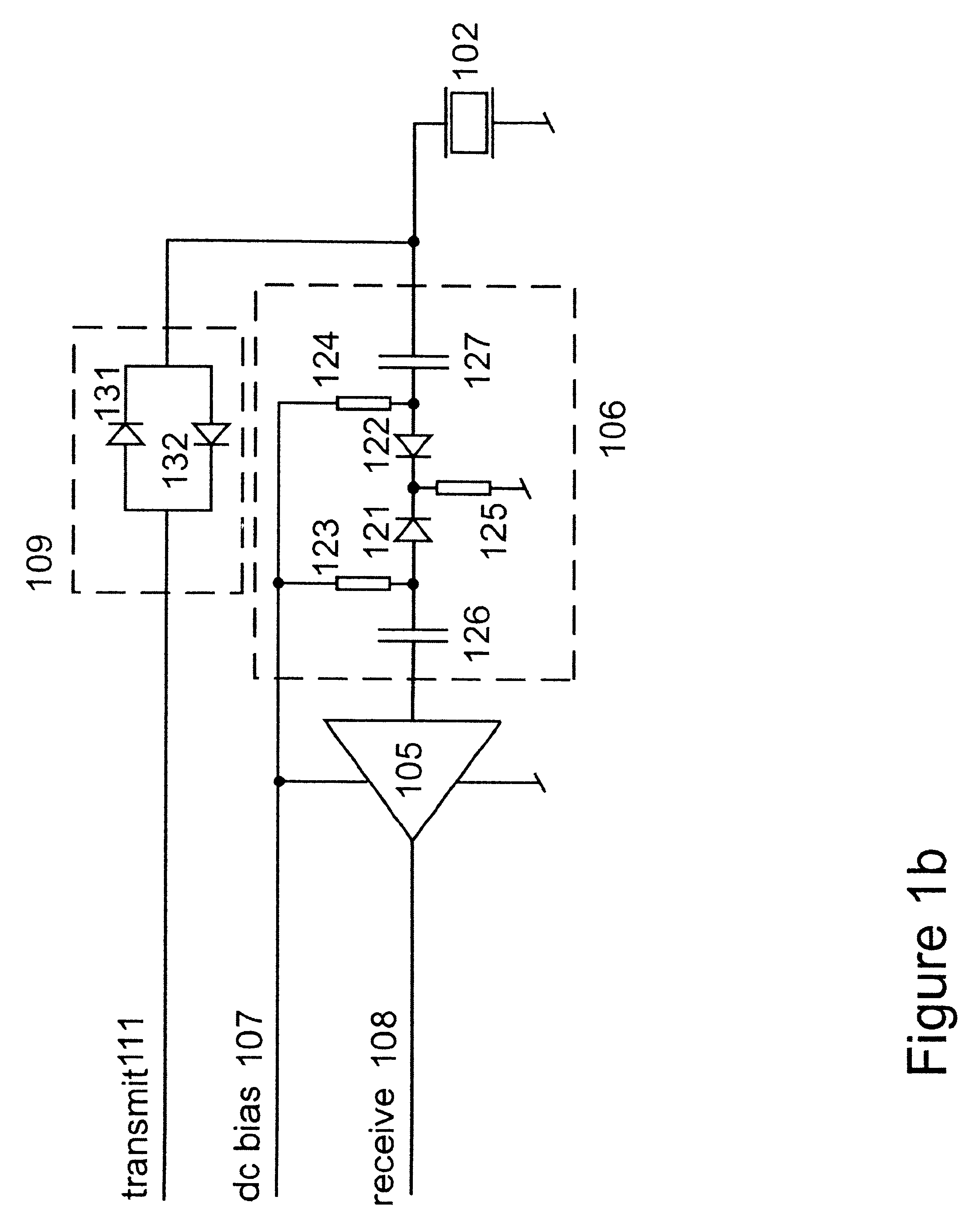
The hot electrode of the transducer element is coupled to the one terminal of a transmit switch 109, where the other terminal is coupled to the output of a transmit pulse buffer 110. High voltage AC...


PUM


Abstract

An advantageous combination of preamplifier electronics and circuits for acoustic beam forming with ultrasound transducer arrays permits integration of the electronics and transducer(s) at close distances in a compact arrangement and is operable from an ultrasound imaging or measurement system using only a minimal number of connecting electric wires. To achieve dynamic focusing of the receive beam with a transducer array, an integrated electronic circuit mounted in close proximity to the transducer array provides preamplifiers for the individual elements and delay circuits that are automatically switched in a predetermined time sequence after transmission of an imaging pulse. When a high voltage pulse is transmitted via the cable, a breakthrough circuit connects the cable to the transducer for transmission of the ultrasound pulse, while in receive mode the low level signal on the transducer is amplified and fed as a higher level signal via the same cable to the imaging or measurement instrument.

Description

1. Field of the InventionThe present invention, relates to high resolution ultrasound imaging of small structures at high frequencies, typically above 5 MHz, where the ultrasound transducer or transducer array is brought close to the structure to be imaged through channels with limited space for cable wires connecting the ultrasound transducer(s) and the ultrasound imaging or measurement instrument.Examples of such applications are intravascular ultrasound imaging (IVUS) of a vessel wall from a transducer at the tip of a catheter, intraurether imaging of the prostate, or high resolution imaging of tumors and small vessels during minimal invasive or other surgery through narrow channels. The invention presents solutions with particularly high signal to noise ratio of the measured back scattered signal, with high inertness to electromagnetic interference from external sources, in such situations.More specific, the invention relates to a design of preamplifier electronics, circuits for...

Claims


Application Information

Patent Timeline
IPC IPC(8): G01S7/52G01S15/00G01S15/89G01S7/521B06B1/02
CPCB06B1/0215G01S7/52025G01S7/5208G01S15/8922G01S7/52079
Inventor ANGELSEN, BJORN A. J.JOHANSEN, TONNI F.
Owner PREXION
Learn More