Dispersion shifted optical fiber

a technology of optical fiber and shifted optical fiber, which is applied in the field of shifted optical fiber, can solve the problems of deterioration of transmission due to non-linear optical effects, difficult to achieve both aeff and dispersion slope reduction, and improve the effect of enlargement of a

Inactive Publication Date: 2003-04-08
THE FUJIKURA CABLE WORKS LTD
View PDF40 Cites 29 Cited by
  • Summary
  • Abstract
  • Description
  • Claims
  • Application Information

AI Technical Summary

Benefits of technology

In the 7 to 12 ps / km / nm range, it is possible to obtain better characteristics than with a conventional NZDSF. Namely, by setting the wavelength dispersion value to be larger than is the case for a conventional NZDSF, it becomes even more difficult for four-wave mixing to occur and it is possible to achieve both an enlargement of the Aeff and a reduction in the dispersion slope, and this range is therefore extremely advantageous.
In the 12 to 15 ps / km / nm range, it is possible to obtain better characteristics than with a 1.3 .mu.m single mode optical fiber. Namely, setting the wavelength dispersion value to be smaller than is the case for a typical 1.3 .mu.m single mode optical fiber, when considering transmission speed and the accumulated dispersion caused by long distance transmissions, is advantageous from the standpoint of system design. Moreover, it is also advantageous when considering the suppression of non-linear optical effect, as it is possible to enlarge the Aeff.

Problems solved by technology

In this case, because of the high intensity of the optical power transmitted through the fiber, the deteriorations in transmission due to non-linear optical effects cannot be ignored.
In wavelength multiplex transmissions, the larger the dispersion slope of the transmission path, the larger the difference in the chromatic dispersion values between each wavelength, the more irregular the transmission state, and the more the overall transmission characteristics are deteriorated.
For example, there are many cases in which the absolute value of the chromatic dispersion value in the vicinity of 1550 nm is equal to or less than 6 ps / km / nm and if the absolute value of such a chromatic dispersion value is set as a small value, the problem arises that it is difficult to achieve both an enlarged Aeff and a reduction in the dispersion slope.
For example, if an attempt is made to sufficiently enlarge the Aeff, then it is not possible to sufficiently reduce the dispersion slope, and if an attempt is made to sufficiently reduce the dispersion slope, then it is not possible to sufficiently enlarge the Aeff.
Therefore, because of the effects from the chromatic dispersion value that accumulate as the optical signal is propagated, the problem has arisen that the transmission distance has been restricted.
Accordingly, the problem has arisen that the transmission characteristics of the overall system have been deteriorated as the used length has increased.
However, if the chromatic dispersion value is made smaller within a range in which the bending loss characteristics necessary in the transmission path can be maintained, the Aeff becomes extremely small resulting in the non-linear optical effect becoming too large.
This results in it being difficult for the single peak type of refractive index profile used in the 1.3 .mu.m single mode optical fiber to be used in an optical communication system using the aforementioned type of high power signal light.

Method used


Image

  • Dispersion shifted optical fiber
  • Dispersion shifted optical fiber
  • Dispersion shifted optical fiber

Examples


example 2

2. EXAMPLE 2

O Ring Type

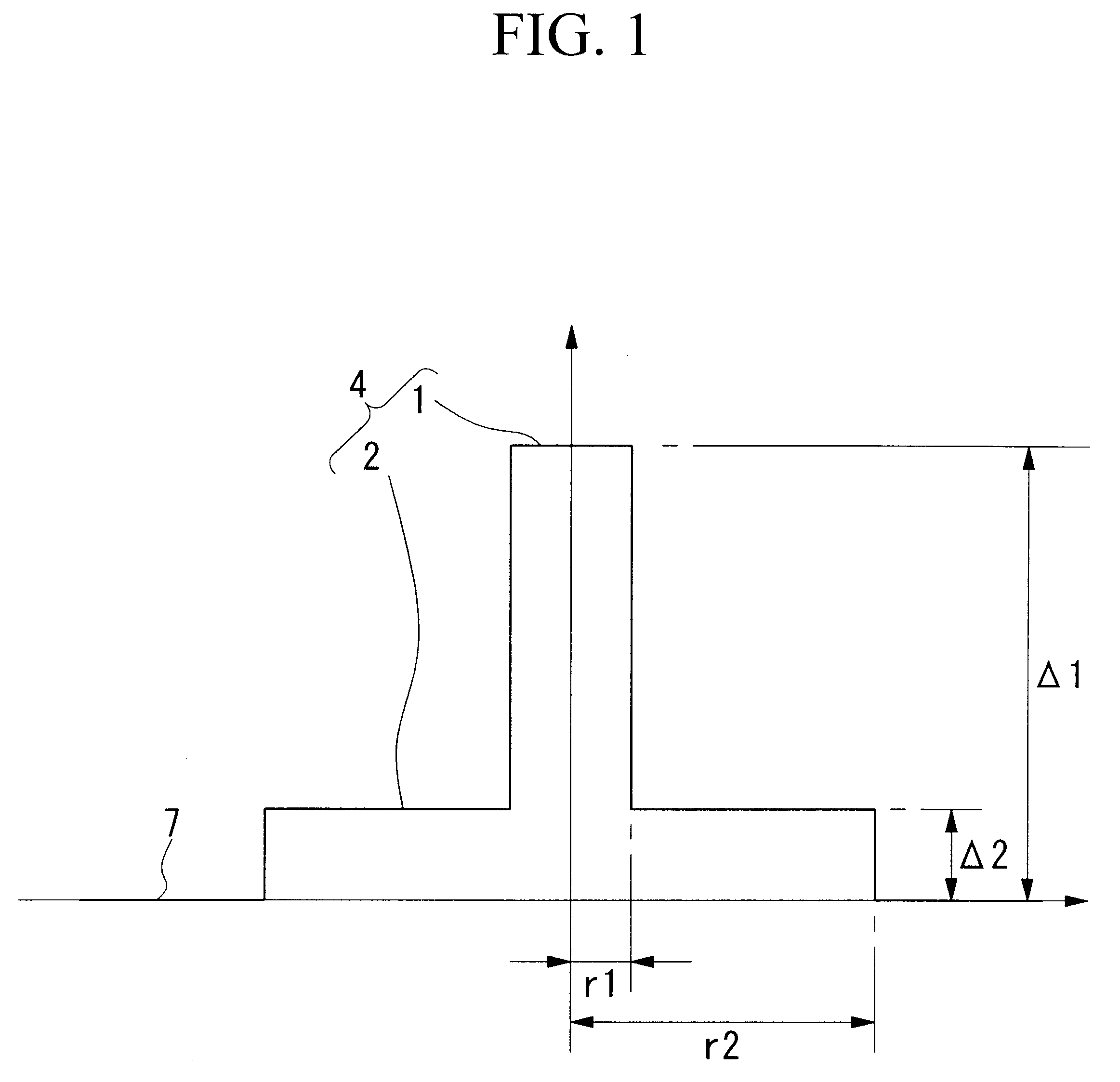
FIG. 2 shows an example of an O ring type of refractive index profile as the second example of the dispersion shifted optical fiber of the present invention.

This refractive index profile comprises a core 34 having a two layer structure formed with a central core portion 31 having a low refractive index in the center thereof and a peripheral core portion 32 having a high refractive index provided at the outer periphery of the central core portion 31. A three layer structure (including the cladding 37) convex type of refractive index profile is formed by providing cladding 37 having a lower refractive index than the peripheral core portion 32 at the outer periphery of the core 34.

In this example, the central core portion 31 is formed, for example, from fluorine doped quartz glass to which fluorine having the function of reducing the refractive index has been doped, the peripheral core portion 32 is formed from germanium doped quartz glass, while the cladding 37 ...

embodiments

The effects of the present invention are shown specifically below using embodiments.

FIG. 6 and Table 3 show the results of the embodiment according to the dispersion shifted optical fiber of the first example. In the present embodiment, dispersion shifted optical fibers were manufactured using the VAD method based on the design conditions of the test sample Nos. 1 and 5 shown in Table 1. In the results, in the present embodiment, chromatic dispersion values from +7 to +11 ps / km / nm were obtained in the C-band selected from the range 1490 to 1625 nm. Moreover, because a chromatic dispersion value that is larger than is the case with a conventional NZDSF is set in the C-band in this way, a chromatic dispersion value that is sufficient for performing wavelength multiplex transmissions in the S-band can be guaranteed. Moreover, because the dispersion slope is small, it was confirmed that the chromatic dispersion value in the L-band was also reduced to a sufficient value.

FIG. 7 and Table ...

second embodiment

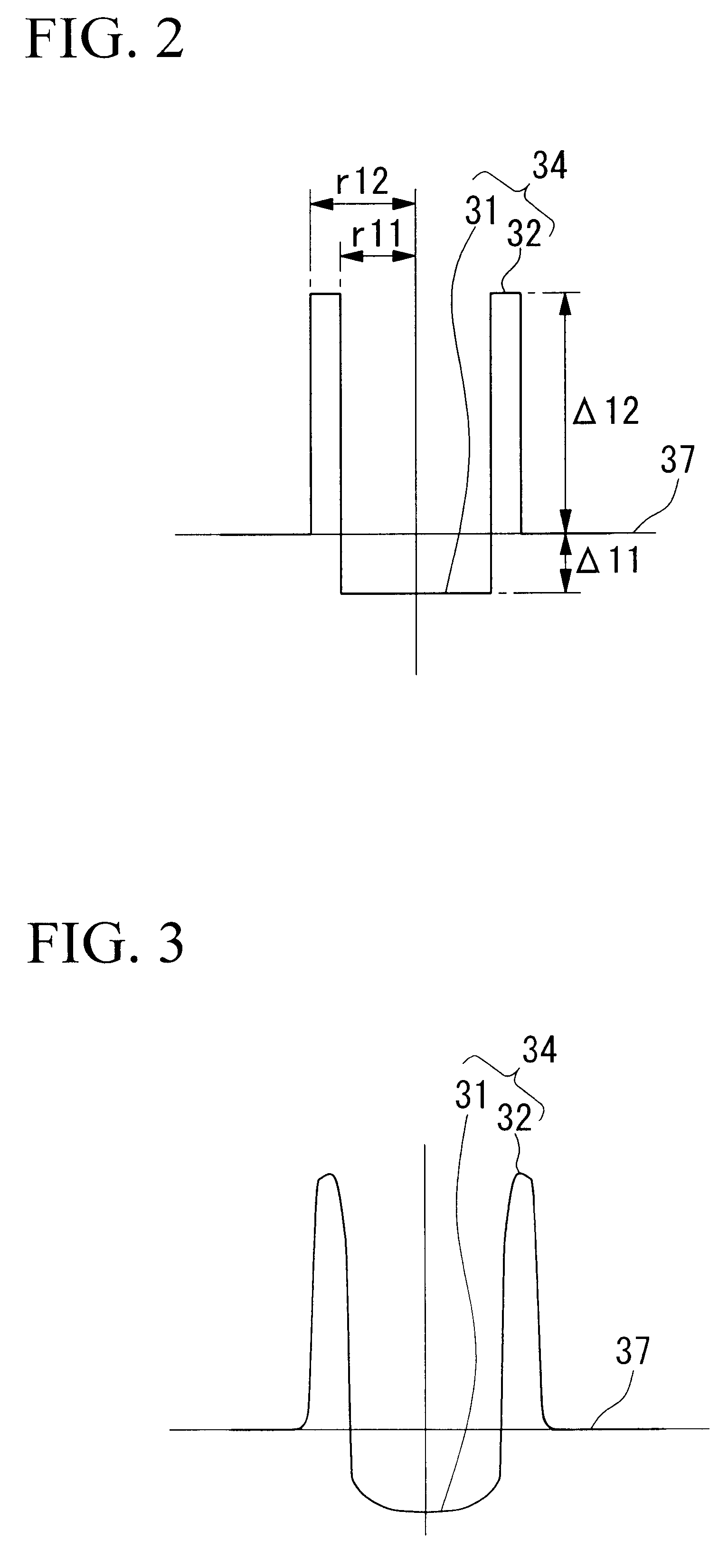
FIG. 8 and Table 5 show the results of the embodiment according to the dispersion shifted optical fiber of the In the present embodiment, dispersion shifted optical fibers were manufactured using the MCVD method based on the design conditions of the test sample 1 shown in Table 2. The refractive index profile is rounded, however, substantially the same characteristic values were obtained as were expected from the design. In addition, a chromatic dispersion value of between +7 and 11 ps / km / nm was obtained in the wavelength band (the C-band in the present embodiment) selected from the above range in the same way as in the embodiment shown in FIG. 6 and Table 3.

FIG. 9 and Table 6 show the results of the another embodiment according to the dispersion shifted optical fiber of the second example. In the present embodiment, dispersion shifted optical fibers were manufactured using the MCVD method based on the design conditions of the test sample 4 shown in Table 2. In the results, it was ...


PUM

PropertyMeasurementUnit
wavelengthaaaaaaaaaa

Abstract

In the present invention, by forming a dispersion shifted optical fiber that has a refractive index profile comprising: a central core portion 1; a step core portion 2 provided at an outer periphery of the central core portion 1 and having a refractive index lower than that of the central core portion 1; and cladding 7 provided at an outer periphery of the step core portion 2 and having a refractive index lower than that of the step core portion 2, and which dispersion shifted optical fiber has, in a used wavelength band that is selected from between 1490 and 1625 nm, chromatic dispersion values of 7 to 15 ps/km/nm, an Aeff of 60 to 150 mum2, a dispersion slope of 0.09 ps/km/nm2 or less, a bending loss of 100 dB/m or less, and a cutoff wavelength that provides essentially single mode transmission, it is possible to reduce the cost of the system and to achieve n improvement in the transmission characteristics.

Description

The present invention relates to a dispersion shifted optical fiber and may be used singly or in combination with a dispersion compensating optical fiber and the like in a transmission path in an optical communication system that uses one type or two or more types of optical fibers, and may also be used for transmitting high power signal light and for performing wavelength multiplex transmissions in the above types of optical communication system.The wavelength with the lowest loss in quartz based optical fibers is in the vicinity of 1.55 .mu.m and, conventionally, this wavelength band has been used for long distance transmissions. As the transmission path (i.e. optical fiber) in this case, generally, a dispersion shifted fiber (DSF) is used that has been designed such that the absolute value of the chromatic dispersion values in the 1.55 .mu.m wavelength band is small.Moreover, optical communication systems that perform division multiplexing on the signal wavelength (WDM) and make ...

Claims


Application Information

Patent Timeline
Patent Type & Authority Patents(United States)
IPC IPC(8): C03B37/014C03B37/018G02B6/036G02B6/02
CPCC03B37/01413C03B37/01807G02B6/03666G02B6/02019G02B6/02238G02B6/03611G02B6/03633C03B2201/02C03B2201/12C03B2201/31C03B2203/36C03B2203/22
Inventor MATSUO, SHOICHIROTANIGAWA, SHOJIABIRU, TOMIO
Owner THE FUJIKURA CABLE WORKS LTD
Why Eureka
Try Eureka