
All optical narrow pulse generator and switch for dense time division multiplexing and code division multiplexing

a technology of code division multiplexing and generator, applied in the field of optical communication, can solve the problems of optical network bottlenecks, limited capability of optical modulators to produce optical pulses, and limited capability of electronic switches

Inactive Publication Date: 2003-08-05
MAIN STREET VENTURES
View PDF14 Cites 10 Cited by
  • Summary
  • Abstract
  • Description
  • Claims
  • Application Information

AI Technical Summary

Benefits of technology

an optical communication system for performing four cooperative functions to enhance data transmission speed: produce very narrow optical pulses in different parallel channels, multiplex the optical pulses of the channels into a single serial bit stream having a very high bit rate, transmit the optical pulse information at a very high bit rate, and demultiplex, at a very high speed, the serial pulse stream back into the original information channels;
all-optical communication system including modulators in several different optical channels for performing three cooperative functions to enhance data transmission density and speed: converting optical pulses into extremely narrow optical pulses in different parallel channels, interleaving the optical pulses of the different channels into one dense serial optical stream of pulses to produce DTDM, and transmitting the pulses, at a very high bit rate, along an optical fiber;
to provide an all-optical communication system including switches, particularly those that are activated by control beams or self-triggered all-optical switches for performing two cooperative functions to enhance the data transmission rate;

Problems solved by technology

On the other hand, there are several components in optical networks that limit the capability of the optical fibers to transmit high-rate and large-volume information and thus cause to bottlenecks in the optical networks.
The optical modulators are limited in their capability to produce optical pulses (logical digital bits) at the desired width and speed and the electronic switches are limited in their capability to switch and route the optical information at the desired rate.
1. The optical fiber has a limited bandwidth (F when it has good optical properties, such as low loss and low chromatic dispersion.
2. The light frequency separation between the different channels is F / .alpha.. Increasing the number of channels .alpha. decreases the light frequency separation F / .alpha. between the channels. The light frequency separation F / .alpha. between the channels must be larger than the line width of the DFB or the DBR lasers which serve as light sources of the channels. Due to the limitation of the line width of these lasers, it is clear that the number of channels J is also limited. Currently the number of channels used (320) is reaching its maximum value.
However the bit rate of this method and others is still limited by the bit rate and duty cycle that the light sources (DFB and DBR lasers) can produce.
1. It has a relatively low duty factor (repetition rate) due to long recovery time of the lasers.
2. It produces chromatic dispersions in the optical fibers due to broadening of the emitted spectral line of the modulated lasers. This is caused by spontaneous emission, jittering, and shifting of the gain curve of the lasers during the current injection.
The charge removal is usually slower and is mainly dependent upon the relaxation time of these materials (lifetime of charge carriers) and can be relatively long.
This bit rate is not sufficient even for the present needs and the demand for a capability to produce and rout faster bit rate will increase in the near future.

Method used


Image

  • All optical narrow pulse generator and switch for dense time division multiplexing and code division multiplexing
  • All optical narrow pulse generator and switch for dense time division multiplexing and code division multiplexing
  • All optical narrow pulse generator and switch for dense time division multiplexing and code division multiplexing

Examples


Embodiment Construction

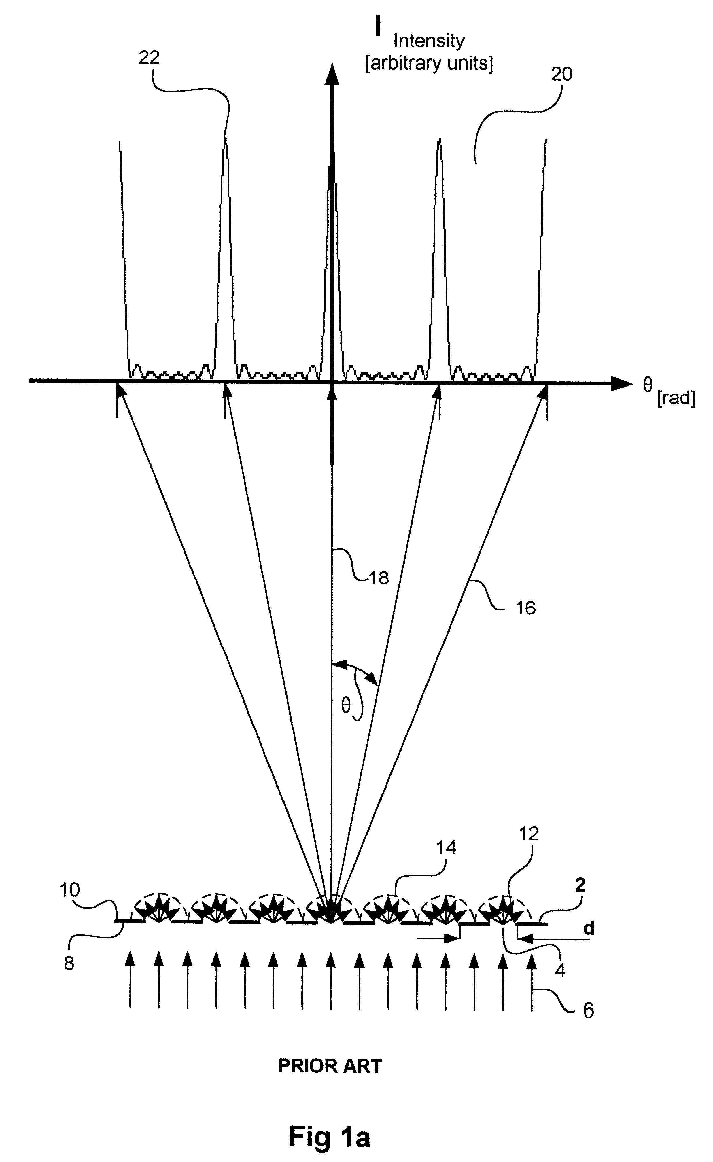
FIG. 1a--Prior Art--Transmitting Grating

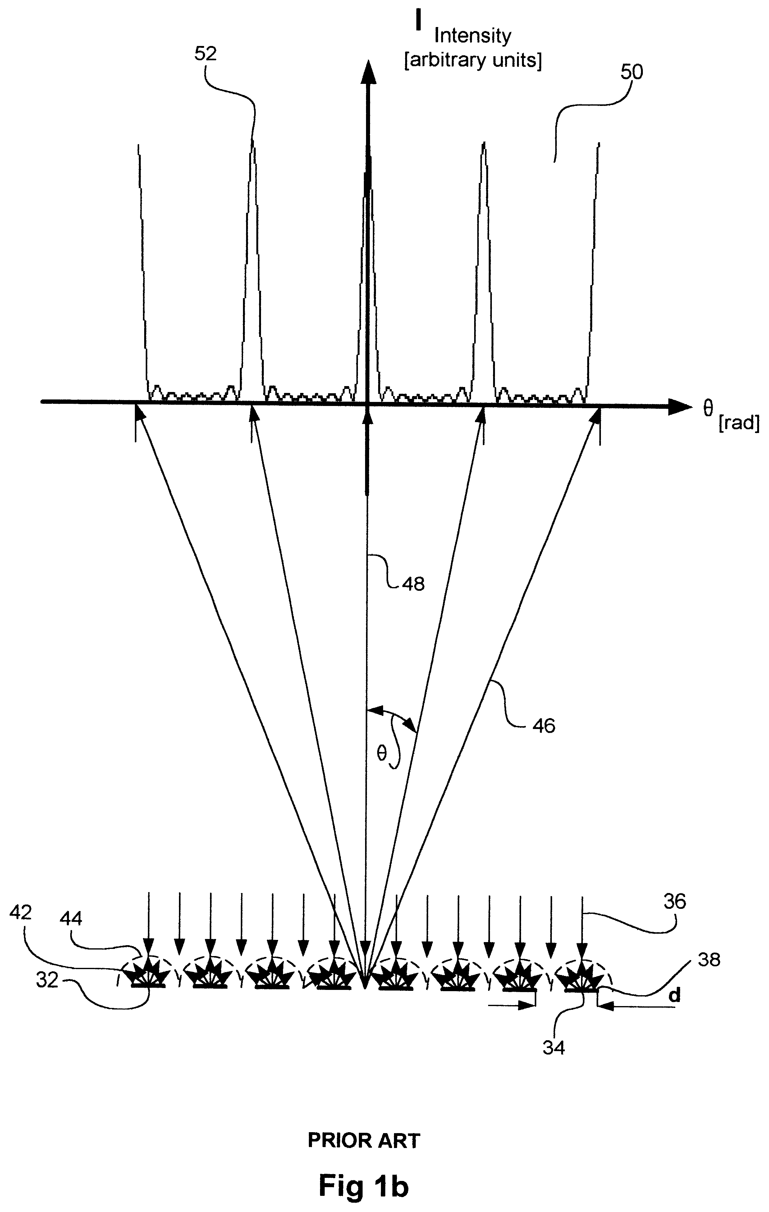
FIGS. 1a and 1b illustrate the optical operational principle of prior-art transmitting and reflecting gratings, respectively. I provide FIGS. 1a and 1b to assist in understanding the present invention.

FIG. 1a shows a transmitting grating 2 with openings 4 with pitch d. Grating 2 receives planar radiation waves 6 on its side 8. Only part of the radiation of waves 6 is transmitted, by openings 4, to the other side 10 of grating 2. Radiation 12 exits from openings 4 and has a spherical front wave (diffraction effect) and its intensity distributed isotropically over half spheres 14 along which it propagates.

The radiation of propagating spheres 14 interfere with each other to create constructive and distractive interference. Arrows 16 schematically illustrate the directions along which the constructive interferences exist. The directions of arrows 16 are indicated by angles .theta., measured in radians, with respect to the axis of symmetry 18 of gr...


PUM

PropertyMeasurementUnit
wavelengthaaaaaaaaaa
optical lengthsaaaaaaaaaa
time widthsaaaaaaaaaa

Abstract

An optical system for modulating and switching logical information-bits in optical communication networks and optical computers. The system includes at least one input, at least one interference device, and at least one output. The interference device receives radiation from the input along multiple orientations at different timings. The interference device produces one interference pattern from a group of different interference patterns so that it can produce a pattern according to the timings, and directs this pattern toward the one output. The output receives the interference pattern produced by the one interference device and selectively emits radiation from the system according to the interference pattern produced according to the timings. The system has two basic versions. In the first version the system operates as an all-optical modulator for generating very short pulses. The second version of the system operates as an all-optical switch. In both versions the system has two operational modes. In the first a control beam activates the system. In the second the system is self-activated. The narrow pulses that the system produces allow the use of Dense Time Division Multiplexing (DTDM) and the self-activating mode of the system allows using Code Division deMultiplexing (CDM) for switching and packet routing.

Description

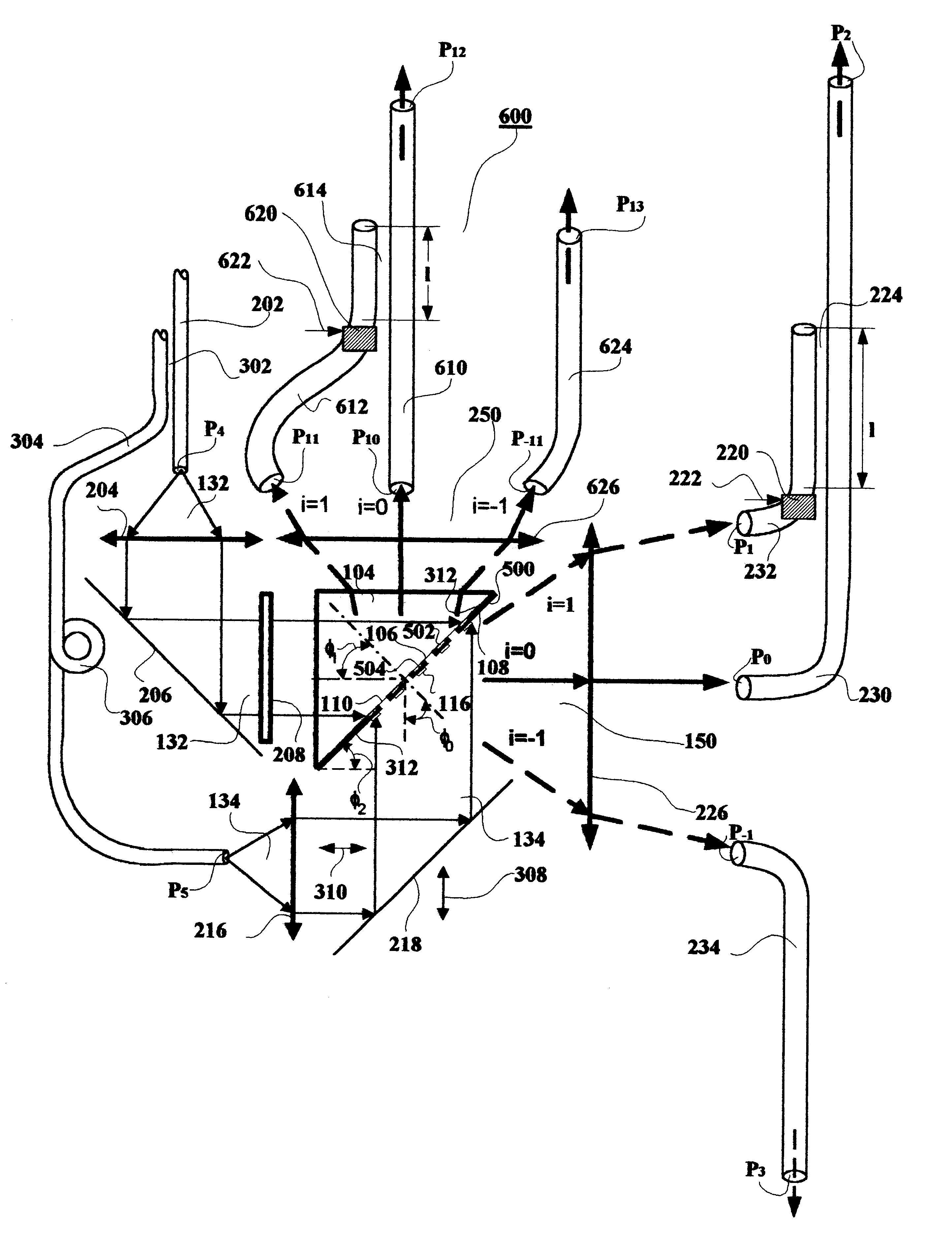
FEDERALLY SPONSORED RESEARCHNoneSEQUENCE LISTING OR PROGRAMNoneBACKGROUND--Field of InventionThe invention relates generally to the field of optical communication, particularly to generating and switching extremely narrow pulses. Such pulses are used generally for ultra-fast optical communication, especially for Dense Time Division Multiplexing (DTDM), Code Division Multiplexing (CDM), and Demultiplexing.BACKGROUND--Prior ArtIn optical communication networks there is a continuous demand for increasing the transmitted information (vocal, video and data) rate and capacity. Optical fibers used in optical networks have a great capability to transmit the required optical-information at high-rate and large-volume. On the other hand, there are several components in optical networks that limit the capability of the optical fibers to transmit high-rate and large-volume information and thus cause to bottlenecks in the optical networks. Such components are the optical modulators and the electr...

Claims


Application Information

Patent Timeline
Patent Type & Authority Patents(United States)
IPC IPC(8): G02B6/34G02F1/31G02B6/28G02F1/29G02F3/00G02B6/35G02B6/26G02B6/12H04J14/08H04J14/00
CPCG02B6/2861G02B6/34G02B6/352G02F1/31G02F3/00G02B6/12009G02B6/266G02B6/2821G02B6/3548G02B6/3556G02B2006/12097G02B2006/12107G02B2006/12147G02B2006/12159H04J14/005H04J14/08
Inventor SHAHAR, ARIE
Owner MAIN STREET VENTURES
Learn More